
FAQs
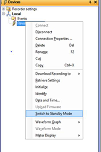
1. If possible, use ProVision to place the recorder in standby mode to stop recording
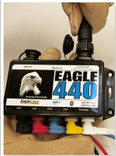
2. Disconnect the CTs from the recorder then remove them from the conductors
3. Remove the common (white) voltage lead from the recorder, and then remove the voltage clip from the conductor
4. Remove the connected voltage leads from Channels 4 (yellow), 3 (blue), 2 (red), and 1 (black) from the conductors, then remove the leads from the recorder
When connecting the recorder, keep the following in mind:
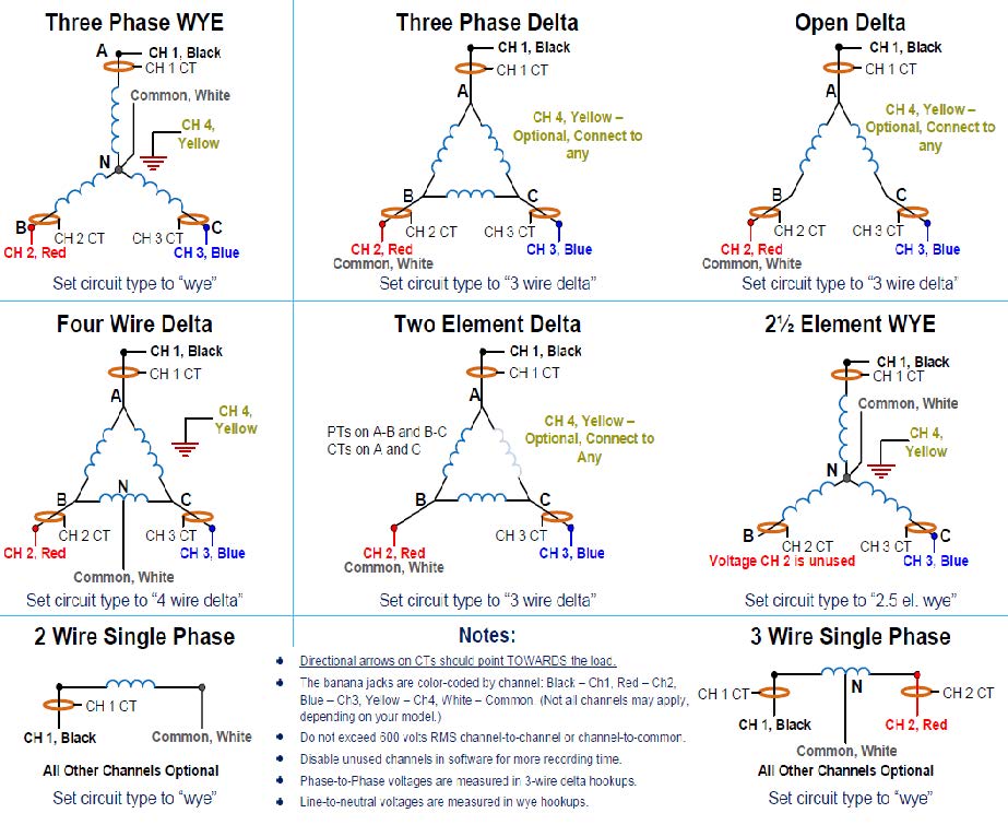
- The banana jacks are color-coded by channel: Black – Channel 1, Red – Channel 2, Blue – Channel 3, Yellow -Channel 4, and White – Common (Not all channels may apply)
- The unit is powered from the voltage between Channel 1 (Black) and common (White)
- Black and white inputs must be connected even if you are not using all the input voltage channels
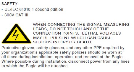
- Do not exceed 600 volts RMS channel-to-channel or channel-to common
When using a three-phase recorder to monitor a single-phase system, either unplug the unused leads and connect them in parallel so that all channels are recording the same information, or clip them to the common connection to avoid noise readings.
- When all CT channels are not required for hookup, unused channels may be connected as desired for additional monitoring.
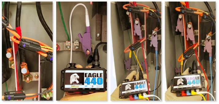
- Wrap the CTs around the conductors with the arrows facing towards the load. Then connect the CT cable to the recorder.
- Connect the common (White) voltage lead to the recorder; and connect the voltage clip to the according to your circuit type.
- Connect the voltage leads for channels 4 (Yellow), 3 (Blue), and 2 (Red) to the recorder; then connect the voltage clips to clip the indicated Channel 2, 3, and 4 conductors.
- Connect the channel 1 (Black) voltage lead to the recorder; then use the dolphin or alligator to attach it to the correct conductor.
Note: It is important to connect the channel 1 voltage lead last, since this will start the two-minute countdown for recording. The LED on the side of the recorder will blink every other second during the two-minute countdown. Once the two-minute countdown is completed, recording begins and the status LED will blink once every six seconds.
The latest firmware listing can be found on the PMI webpage under the Support page or directly at: https://powermonitors.com/firmware-chart/
You can see the recorder Firmware version on the header reports in Provision.

In Provision, if you have a recorder connected to your PC, you can visit the Recorder tab and select Identify, then select the View button that pops up.


In the listing that displays will be the Firmware of the recorder.

In Provision the Upgrade Manager, keeps the latest firmware on your PC up to date. Your IT can block this feature.
Select the Help tab in Provision, then select ‘Check for updates’

In the Firmware section of the popup, it will display how many Firmware files are not on your PC.

Allow the Upgrade Manager to load the missing Firmware files on your PC.

Provision will compare the Firmware on your PC to any recorders that are connected. After a download of the data file, Provision will ask if you want to update the Firmware if the Firmware is different.
How to manually update Firmware in an Attached Recorder
Connect recorder
In Provision select Options -> Show Advanced Operations

In Provision select Recorder -> switch to standby mode (if shown)

In Provision select Recorder -> Upload firmware

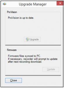 Recent versions of ProVision include the Upgrade Manager which allows the user an easy way to ensure that the ProVision software and the recorder firmware are up-to-date. The Upgrade Manager is displayed when ProVision is started. Selecting the Upgrade button, when a new ProVision version is available, will close, update and reopen Provision. Selecting the Update button, will copy the firmware files to your PC. To hide the Upgrade Manager, select the Menu Options tab and Preferences, then de-select ‘Check for Updates on Startup’. The Upgrade Manager can be manually opened by selecting the Menu Help tab and ‘Check for Updates’.