Abstract
While three-phase AC squirrel-cage motors have been around and reliable since 1889, courtesy of Mikhail Dolivo-Dobrovolsky, one issue that has plagued their operation and lifespan throughout the years has been voltage unbalance. These induction motors are designed to have all three phases of their windings balanced when in operation, ensuring cool operating temperatures and a long service life. However, the introduction of voltage unbalance to these motors is detrimental, with even small percentages creating a recipe for a catastrophic failure if left unchecked.
What Are Voltage Unbalances and How Do They Happen?
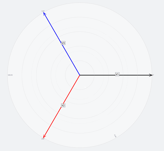
In an ideal three-phase electrical system, all phases are balanced with respect to one another. All three phases have the same voltage and current amplitudes and are 120° out of phase from each other. Figure 1 shows an example of a balanced voltage system – all phases are 120° from each other and share the same magnitude of 500VAC. A motor operating on this voltage supply will enjoy a long service life, so long as balance is maintained.
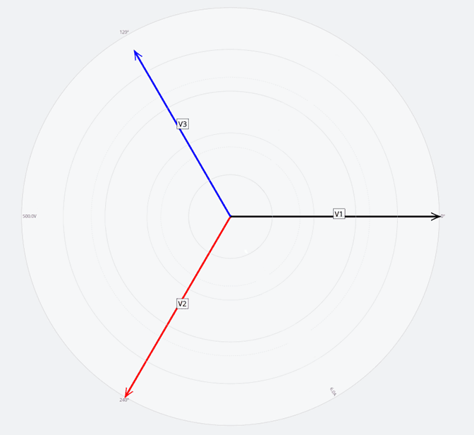
A voltage unbalance is where one or more of the phases in the three-phase system are not equal to the others. As seen in Figure 2, voltage unbalance is present due to the Channel 3 (V3) phase showing a lower voltage present than the other channels. Unbalances like this are prevalent in large industrial facilities due to the powerful machines and motors that are required to perform the processes modern-day manufacturing demands.
Typically, voltage unbalance in a facility is caused by poor system load distribution. This is to say that most imbalances occur from single-phase loads not being spread out over all three phases of the system properly. The most common of these loads being related to heating/cooling functions or single-phase motors as they are often hooked up where one conductor carries more current than the others. This instance creates a lower voltage on a single phase, resulting in the other two phases having a higher line-to-neutral voltage. This difference in line-to-neutral voltage also results in a line-to-line voltage differential. While poor load distribution may be common inside a facility, not all voltage unbalance issues are caused by customer-installed loads. Some voltage unbalance causes that are not created by load distribution in a facility can include the following:
- Open wye or delta transformers
- High current three-phase loads
- Under-sized transformer banks for a three-phase load
- Single-phase-to-ground faults
- Loose or corroded connections
- Lack of transmission line transposition
How Is Voltage Unbalance Calculated?
The ability to calculate voltage unbalance to ensure a motor can operate as designed is critical. One method utilized for calculating unbalance in a three-phase system is laid out by ANSI C84, utilizing line-to-line voltages and the formula seen in Figure 3:
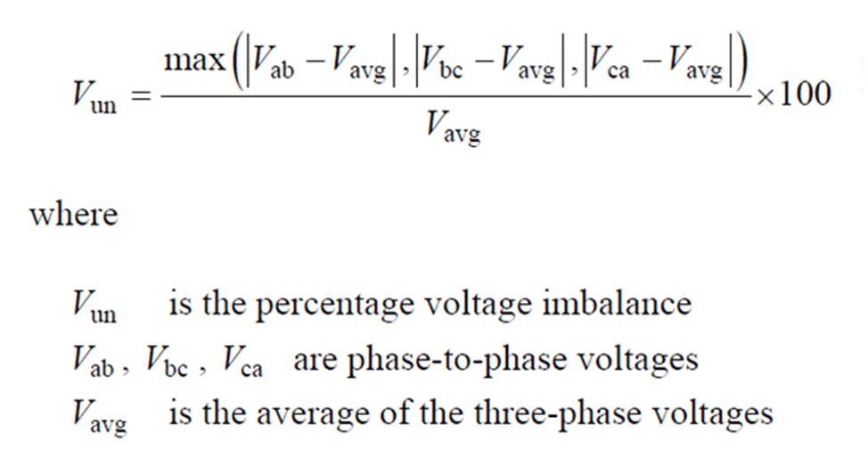
To see this in action, consider the following line to line voltages:
- L1 → L2: 480V
- L2 → L3: 465V
- L3 → L1: 490V
In this case, our nominal line-to-line voltage is 480V. Comparing our line-to-line voltages, we see two deviations from nominal: L2 → L3 with 15V low and L3 → L1 with 10V high. Given 15V is a greater deviation than 10V, we will utilize this for our calculation. In this system, our average voltage is 478.33V for an approximate voltage unbalance of 3.13%. While this may not seem large percentage wise, NEMA considers less than a 1% unbalance as ideal and anything larger than a 2% unbalance as unacceptable. If a system has a voltage unbalance of 5% or greater, it is not recommended to operate a motor on this system whatsoever.
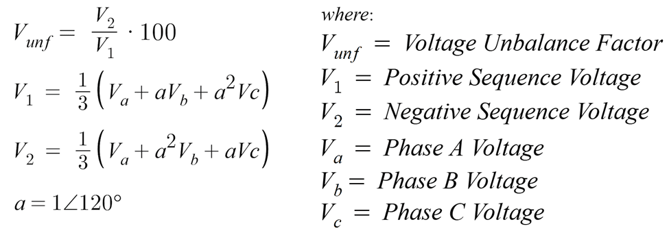
While the ANSI C84 method for calculating unbalance is an easy-to-compute formula that utilizes RMS voltage measurements, it does not take into account phase angle errors or wye readings and works best on a delta setup. The most accurate method for calculating voltage unbalance is utilizing the symmetrical components method (Figure 4). Using this method, you will get the same reading for both a delta or wye connection and accounts for phase angle measurements. This method, however, is more difficult to compute, because it considers these variables.
How Does Voltage Unbalance Affect Motors?
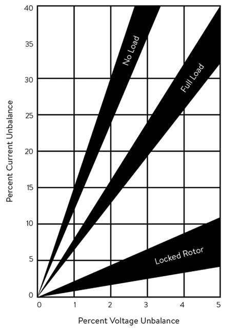
Although a small voltage unbalance may seem like a non-issue, it can cause many issues for polyphase induction motors. These can include reduced speed, reduced torque output, excessive noise/vibration, and temperature rise beyond what the motor was designed to operate in. Another byproduct of this voltage unbalance is that the currents drawn by the motor will be unbalanced as well, though the current unbalance is a far greater percentage than the voltage unbalance – usually six to ten times the voltage unbalance. Figure 5 shows a visual representation of the relationship between voltage unbalance and current unbalance percentages. The motor’s current increase is due to the introduction of a negative sequence voltage on the motor causing a flux rotating against the rotor’s rotation to propagate in the air gap. In other words, the negative voltage sequence is actively trying to rotate the motor the opposite direction it is running – a less than ideal scenario.
Even small negative sequence voltages can produce currents in the motor windings that far exceed those that are observed during normal, balanced conditions. For instance, a 3.13% voltage unbalance can result in a 37-40% current unbalance under no load, a 22-24% current unbalance under full load, and a 3-6% current unbalance under locked rotor conditions (Figure 5). We also see in Figure 5 that a voltage unbalance of only 1% can result in a current unbalance of 6% under full load conditions! This current unbalance can also result in the nuisance trips of overload devices, as they experience the current unbalance, as well. When a motor is operating in an unbalanced voltage condition, one should size the overload protection to respond to the maximum anticipated current in lieu of the average anticipated current.
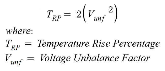
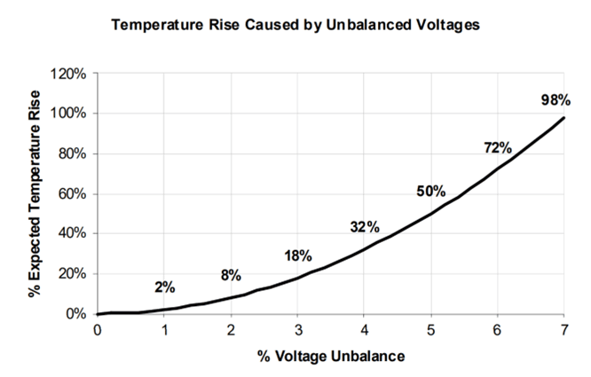
Perhaps the largest concern with unbalanced voltage is the temperature rise it causes in the motor. When comparing a motor’s temperature rise under identical loads in a balanced and unbalanced voltage condition, it is found that the temperature will increase far more in the unbalanced voltage motor than the balanced voltage motor. To find the temperature rise a motor will experience, use the formula in Figure 6. This is reflected in the plot in Figure 7.
Referring to our example motor from earlier that was operating under a 3.13% voltage unbalance condition, it will experience a temperature rise of a staggering 19.59%. If the motor was designed to operate at 30°C under normal conditions and was doing so, being exposed to this unbalance would cause the temperature to climb to 35.87°C with no other conditional changes. While this may not seem like a large increase, it will cost the windings approximately 25% of their lifespan. This reduction is because for every 10°C over the designed operating temperature that a motor’s windings are subjected to, the lifespan of the windings is cut in half. Due to the fact that our example motor saw a 5°C rise over designed temperature, the lifespan is cut by 25% versus 50%.
It may not always be possible to eliminate voltage unbalances, therefore technicians and engineers should take motor derating into account. This derating is required to help preserve these motors and to prevent them from failing prematurely. Per NEMA MG-1, the derating factor should follow Figure 8. Using this table, and our example unbalance percentage of 3.13%, the motor’s rated horsepower (HP) should be multiplied by the derating factor of 0.88. For example, if the motor was a 10HP motor driving a clutched lathe in a machine shop, the voltage unbalance would limit the motor to a rating of 8.8HP.
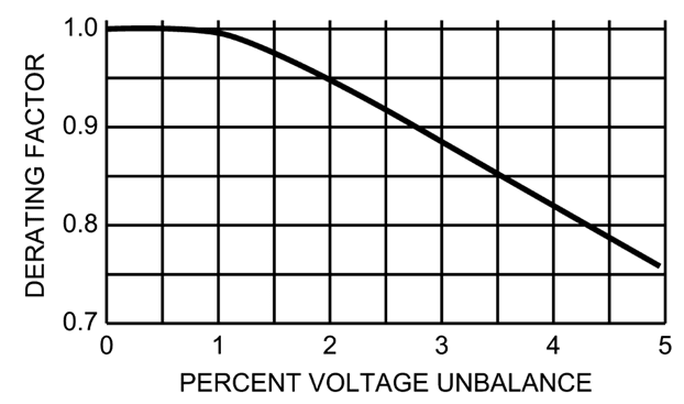
In this case, the motor would have to be sized up to approximately 11.5HP in order to allow the machine to utilize an effective 10HP when in operation.
How to Detect Voltage Unbalances?
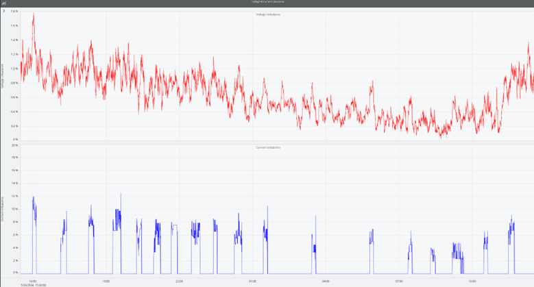
Voltage unbalances can be hard to track down as they can fluctuate with differing loads in a facility, the time of day, or even the weather. This results in difficulty for a technician to observe the system when the unbalance is its worst and is also cost prohibitive to continue sending them out for periodic checks. Utilizing a high-resolution PQ recording device that can be left in the field and remotely report back data gives real-time data to engineers to be able to detect and help mitigate unbalance issues faster. By using PMI’s PQ Canvass, not only can you remotely monitor what is occurring at the deployment site for a recorder, but you can upload a PQ recording for analysis. Figure 9 showcases a visual representation of the voltage unbalance and current unbalance experienced for a recording.
Conclusion
Voltage unbalances, while small at times, can cause large-scale and costly issues if not discovered and accounted for. Not only can they be devastating to AC motors, they can also affect three-phase rectification loads such as variable frequency drives. See our white paper, Voltage Tug-of-War: The Silent VFD Killer, for more information on the specific issues and damages that voltage unbalances can cause in VFDs. Being aware of how voltage unbalances can affect components not only helps keep undesired downtime to a minimum, but reduces the chance for premature failure when mitigation techniques are utilized.
