
Abstract
The modern variable-speed drive (VFD) is a sophisticated power electronic system, yet the front end is still a deceptively simple six-pulse diode bridge. That simplicity means the rectifier has little innate tolerance for upstream phase voltage disparity. Even a few percent of supply voltage unbalance upsets the equal sharing of current between the six diodes, sets up elevated ripple on the DC bus, and ultimately accelerates wear of both the rectifier itself and the DC-link capacitor bank. When unchecked, those stresses propagate downstream and shorten the life of the variable-frequency drive motor it supplies. A typical VFD is shown below in Figure 1.
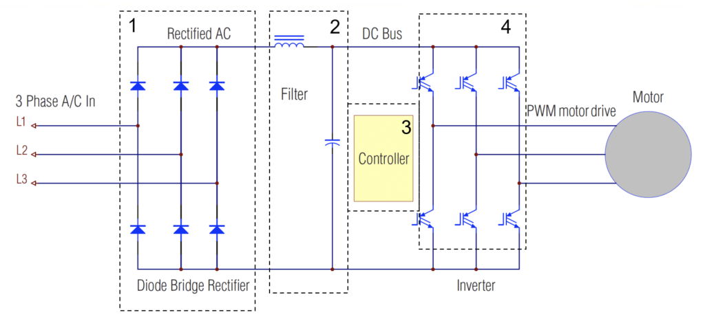
Voltage Unbalance Effect on Components
In a balanced system each line-to-line voltage successively exceeds the DC-link potential by the same margin, so the six diodes conduct identical current pulses. A voltage unbalance of only 1% is enough to skew pulse heights measurably; at 5% the tallest pulse can carry twice the current of the shortest. The diodes with the highest voltage see a higher current and thus temperature is increased. Diode lifetime is reduced significantly when at higher temperatures. The hotter diode pairs then drop slightly less forward voltage, which invites still more current and still more heat—a positive feedback path known as thermal runaway.
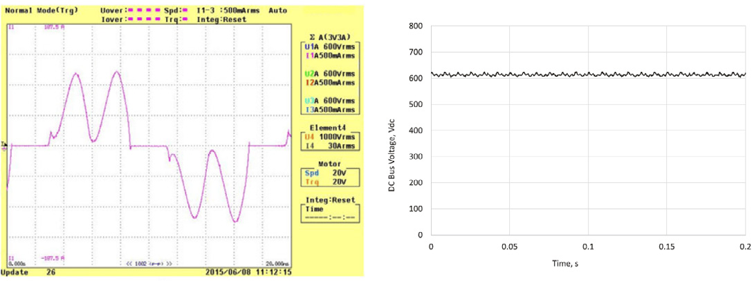
The DC-link capacitor is designed for a defined ripple current at 360 Hz (six times line frequency). As unbalance grows, the ripple component of the DC bus voltage also grows. Within Operation of Variable-Frequency Drive Motor Systems With Source Voltage Unbalance, tests on a 7.5 hp drive show Vripple climbing from 3.5% at balanced conditions (Figure 2) to 18.6% at 5% unbalance (Figure 3), while the mean bus voltage rose from 614 V to 627 V.
Together these increases force more RMS ripple current through the capacitors, causing the capacitor-heating factor (CHF) to escalate steeply and curtail service life. Capacitor heating is one of the dominant mechanisms linking supply unbalance to premature DC-link failure.
When the capacitor degrades, ripple voltage escalates further, creating a vicious cycle that eventually trips the drive on DC-bus over-voltage or blows the link fuse.
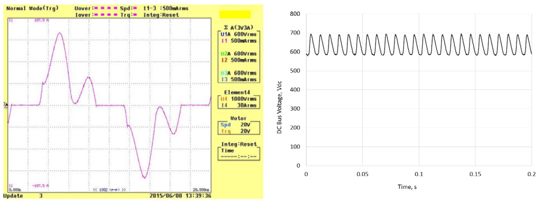
Heightened ripple not only stresses the capacitor but also increases the instantaneous peak of the DC bus by as much as 100 V in a 480 V system at 5% unbalance. The IGBTs or SCRs in the inverter must now block this higher voltage with every switching event, bringing them closer to their collector-emitter sustaining voltage rating and thinning their safe operating margin.
The resulting over-voltages propagate to the motor terminals as faster, higher spikes; combined with long lead lengths they can erode winding insulation and cause partial discharge.
Meanwhile, unequal diode conduction introduces non-characteristic triplen harmonics into the DC link, which the inverter reflects as torque pulsation and acoustic noise. Motor heating caused by negative-sequence voltages is well documented: a 2% unbalance at full load can raise winding temperature 30°C and halve insulation life.
Using PMI’s Devices to Detect and Resolve Voltage Unbalance
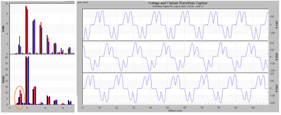
Because diode current pulses are narrow (60 electrical degrees) high-resolution waveform capture is invaluable. PMI Revolution, Seeker, or Bolt PQ monitors readily resolve the pulse train. Record RMS voltage, voltage THD, and voltage unbalance concurrently with RMS current, current THD, and current unbalance; enable magnitude for harmonics 3–15 as they highlight triplens. Figure 4 shows triplen harmonics recorded by a PMI Revolution, caused by voltage unbalance creating increased harmonic current levels for VFDs.
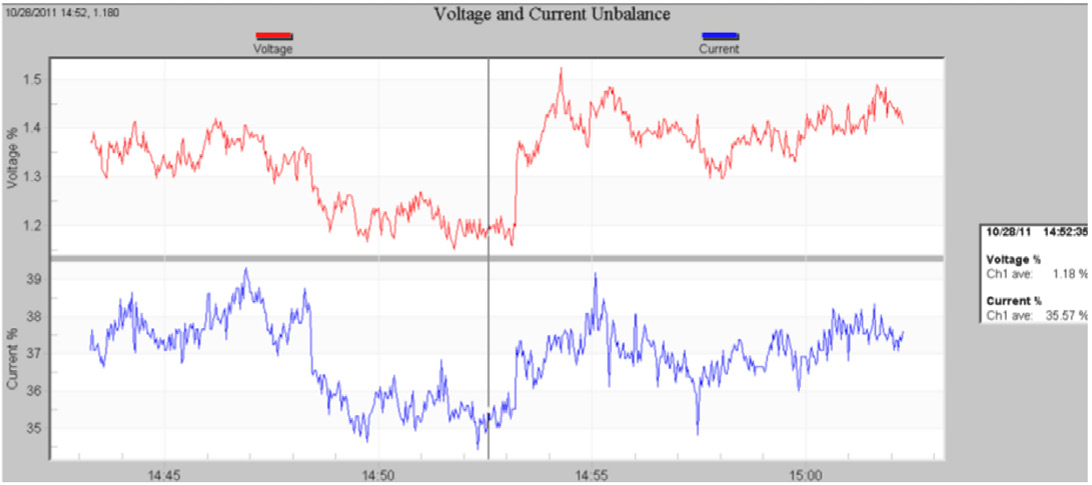
An ANSI C84-style interval plot (Figure 6) of voltage unbalance overlaid with the corresponding current unbalance ratio reveals whether the drive is the victim or the perpetrator: if current unbalance is ten to twenty times the measured voltage unbalance the source is likely balanced and the bridge is failing; if both metrics rise together the supply is suspect.
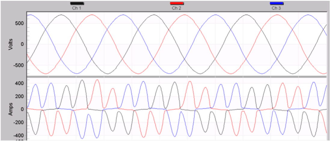
PMI’s PQCanvass and Provision software automatically computes these ratios and flags excursions. Figure 5 shows a waveform capture captured by a PMI Seeker. Viewing this waveform capture it is easy to tell that the voltage waveforms appear to be uniform, but the current waveforms are not very symmetrical. That is where the unbalance ratio interface (Figure 6) comes in handy. In Figure 6 the voltage unbalance is between 1–1.5%, but the current unbalance is above 35% which points to the source likely being unbalanced.
Mitigation and Maintenance for Voltage Unbalance
The least-cost remedy is correcting the cause of the supply unbalance: open delta secondaries, single-phase transformer banks, unequal single-phase loads, or blown capacitor-bank fuses. Where load diversity prevents perfect balance, series impedance smooths the disparity. DC-link chokes, if not already present, reduce capacitor RMS current and dv/dt to the inverter.
For critical drives, derating remains prudent: NEMA MG-1 suggests reducing motor load to 95% at 2% unbalance, 88% at 3%, and 82% at 4%; the VFD manufacturer should supply an equivalent curve. Active Front End (AFE) converters, while costlier, employ controlled switching to equalize diode currents and compensate modest supply asymmetry, though performance varies with vendor algorithm. On larger feeders a D-STATCOM can inject the missing negative-sequence voltage and restore balance locally.
Conclusion
Voltage unbalance is a small-signal imperfection with large-signal consequences in six-pulse rectifiers. Unequal phase magnitudes and angles drive disproportionate diode current, accelerating diode and capacitor heating, amplifying DC-bus ripple, and stressing inverter switches and motor insulation.
Early detection via high-resolution PQ recording, prudent derating, supply-side balancing, and targeted filtering together form an effective defense.
Utility engineers armed with the monitoring strategies and mitigation hierarchy outlined here can resolve customer complaints, extend motor-system life, and maintain compliance with emerging IEEE voltage-imbalance practice.