
Introduction
Voltage imbalance, also referred to as voltage unbalance, is an important power quality issue that can lead to significant operational problems in customer equipment. It occurs when the magnitudes or phase angles of the three-phase voltages are not equal. While the primary concern with voltage imbalance is its impact on motor efficiency and equipment lifespan, it also introduces waveform distortion, which can increase voltage harmonic levels, increase losses, and negatively affect sensitive loads.
Definition and Causes of Voltage Imbalance
Voltage imbalance is typically quantified using the National Electrical Manufacturers Association (NEMA) and IEEE definitions, with the most common metric being:
where Vmax is the highest phase voltage, Vavg is the average phase voltage, and Vu represents the percentage imbalance.
Causes of voltage imbalance include:
- Uneven distribution of single-phase loads on a feeder
- Open delta and high-leg delta services
- Faulty or degraded components such as transformers, capacitors, or wiring
- Blown cap bank fuses
Mechanisms of Waveform Distortion Due to Voltage Imbalance
Voltage imbalance impacts waveform distortion through several interrelated mechanisms:
1. Introduction of Negative Sequence Components
A balanced three-phase system ideally consists of only a positive sequence component. However, voltage imbalance introduces negative sequence components that circulate in opposite directions to the fundamental frequency. This distortion affects the waveform symmetry and increases losses in induction machines. For more detailed information on symmetrical components and methods for computing them with PMI’s PQ recorders see WP371 Symmetrical Components and WP374 Symmetrical Components from Stripchart data.
2. Harmonic Multiplication and Injection
Voltage imbalance alters the harmonic spectrum of an electrical system. Specifically:
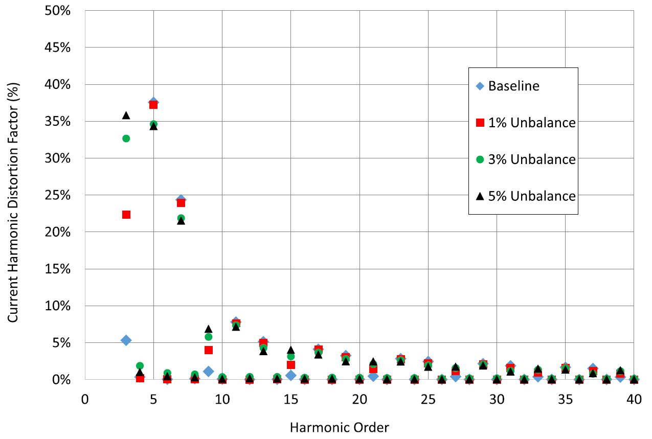
- It increases triplen harmonics (third, ninth, fifteenth, etc.), which do not cancel in a three-phase wye system and accumulate in the neutral conductor.
- It exacerbates the fifth and seventh harmonics, which induce torsional oscillations in rotating machines.
- It introduces interharmonics and subharmonics that can interfere with frequency-sensitive loads such as variable frequency drives (VFDs).
3. Rectifier and Inverter Nonlinearities
Modern power electronics rely on rectifiers and inverters, which inherently produce harmonic distortion in the rectification process. Under balanced conditions, these devices exhibit predictable distortion characteristics. However, with voltage imbalance:
- The conduction periods of diodes and transistors vary between phases, distorting the output waveform.
- DC bus ripple increases, leading to greater output voltage fluctuation in inverters.
- Additional frequency components appear, impacting downstream sensitive equipment.
4. Increased Transformer Saturation and Core Losses
Voltage imbalance leads to asymmetric magnetization in transformers, causing unbalanced core saturation. This results in:
- Increased harmonic generation due to non-sinusoidal magnetizing currents.
- Overheating and derating of transformers due to higher eddy current losses.
- Amplification of existing waveform distortions through nonlinear impedance interactions.
Transformer Saturation
More specifically, the core of a transformer is made of magnetic material, usually iron or steel, that channels the magnetic flux created by the alternating current in the windings. Under normal conditions, the flux oscillates symmetrically around zero, and the core’s magnetic properties stay within a sweet spot called the linear region of its magnetization curve (the B-H curve). When voltages are unbalanced, though, the flux doesn’t behave as nicely.
Unbalance introduces uneven currents and voltages, which can produce a net DC component or exaggerate the flux in one direction. This pushes the core closer to—or past—its saturation point, where the magnetic material can’t handle more flux without a disproportionate increase in magnetizing current. Think of it like overfilling a bucket: once it’s full, any extra just spills over messily. In saturation, the core stops responding linearly, and you get a spike in current draw, distortion in the waveform (harmonics), and potentially a lot of wasted energy.
Core Loss
Core losses come in two flavors: hysteresis losses (energy lost flipping the magnetic domains in the core) and eddy current losses (heat from currents induced in the core material). Voltage unbalance cranks both up. When the core saturates, the hysteresis loop—the cycle of magnetization—widens because the material is being driven harder, losing more energy per cycle. Eddy currents also spike because the distorted flux induces stronger, erratic currents in the core. The result? More heat, more inefficiency, and a transformer that’s working harder than it should.
Real-World Impact
Even a 2–3% voltage unbalance can double or triple core losses in some cases, depending on the transformer’s design and load. It also stresses the insulation (from heat) and can shorten the transformer’s lifespan. On top of that, the harmonics from saturation can ripple back into the power system, tripping up other equipment. For utilities or industrial setups, this is a big deal: efficiency drops, costs rise, and you might even hear the transformer humming or buzzing from the extra magnetic forces.
Experimental Observations Using Power Monitors, Inc. (PMI) Equipment
PMI power quality recorders such as the Bolt and Seeker provide insights into voltage imbalance and resulting waveform distortions through:
- RMS Voltage Stripcharts: Identifying sustained or transient imbalance.
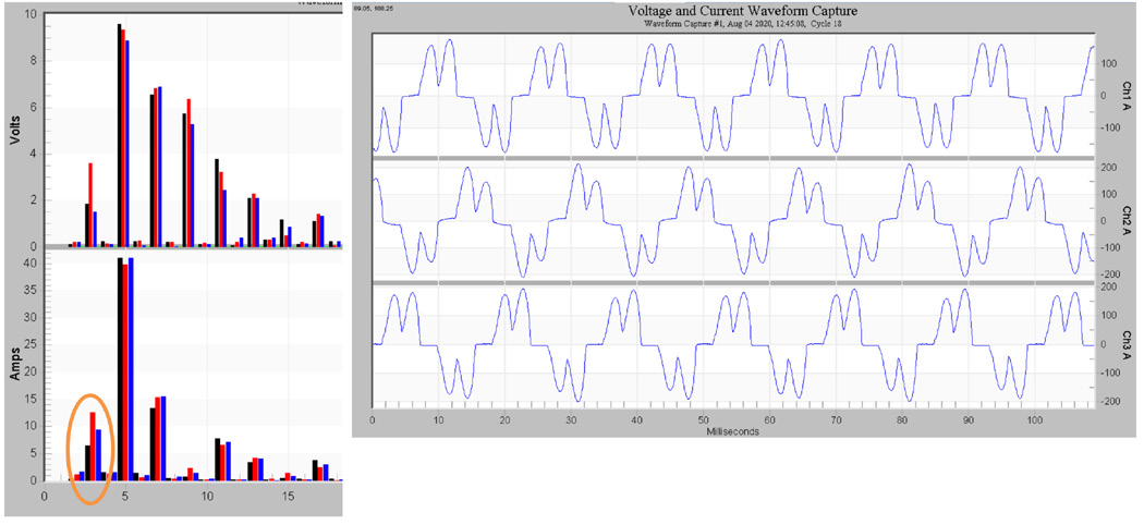
- Waveform Capture: Detecting deviations from sinusoidal operation.
- Harmonic Analysis Reports: Quantifying increases in harmonic distortion levels due to imbalance.
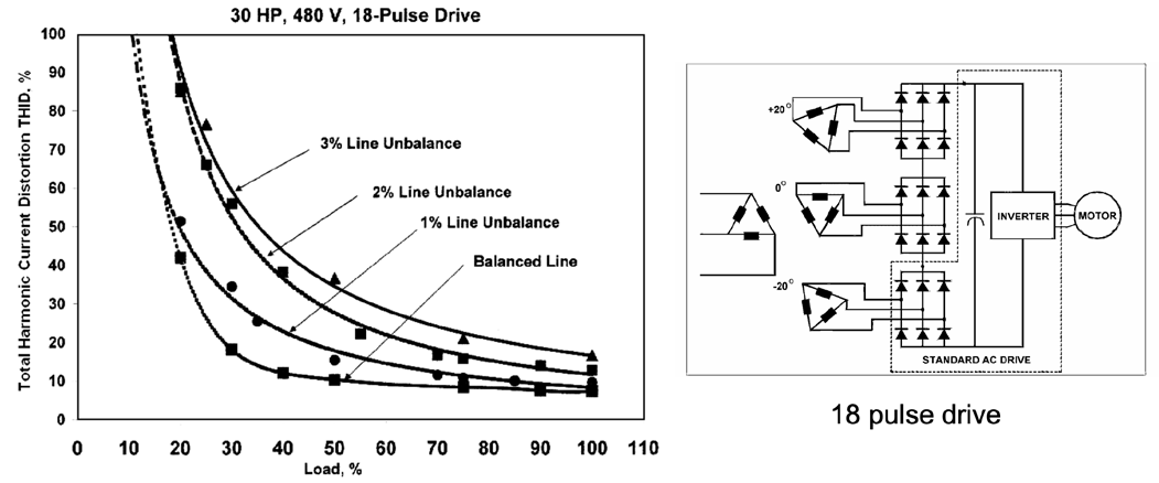
In field cases, a voltage imbalance as small as 2% led to:
- A 20% increase in total harmonic distortion (THD) on the affected phases.
- A rise in neutral current by up to 150% due to accumulated triplen harmonics.
- A 3–5% reduction in motor efficiency due to additional losses in rotor and stator windings.
Emmanuel B. Agamloh , Senior Member, IEEE, Scott Peele, Member, IEEE, and Joseph Grappe, Member, IEEE
IEEE TRANSACTIONS ON INDUSTRY APPLICATIONS
VOL. 53, NO. 6, NOVEMBER/DECEMBER 2017
Mitigation Strategies
Addressing voltage imbalance to minimize waveform distortion involves:
- Load Balancing: Distributing single-phase loads more evenly across all three phases, both at the feeder level and customer level.
- Voltage Regulation: Using automatic voltage regulators or tap-changing transformers to stabilize voltage variations.
- Power Factor Correction Adjustments: Ensuring capacitors are properly sized and balanced across phases.
- Active Harmonic Filters (AHF): Mitigating harmonic propagation from non-linear loads exacerbated by imbalance.
- Preventive Maintenance: Regularly inspecting wiring, connections, and transformer health.
Conclusion
Voltage imbalance is a significant contributor to waveform distortion in power systems. It introduces negative sequence components, exacerbates harmonic content, and reduces equipment efficiency. Monitoring and mitigating voltage imbalance using PMI recorders and IEEE/NEMA standards-based approaches can enhance power quality and improve system reliability. Addressing this issue is crucial for maintaining optimal electrical performance in utility and industrial settings.