Abstract
A new method of triggering waveform capture in the Revolution and Vision is introduced, designed for capturing changes in power line waveform shape.
Overview
Traditional waveform capture trigger mechanisms often relied on magnitude changes in line voltage, either from RMS voltage, or instantaneous line voltage changes. Although good for capturing events associated with voltage sags, swells, faults, etc., this method is difficult to use with events that don’t always cause a line voltage change. For example, a capacitor bank switch operation can cause waveform ringing, or voltage phase changes, without actually changing the overall RMS voltage level appreciably. If the thresholds are set so sensitively that those events are captured, many false triggers can also be generated for innocuous events.
Other manufacturers have attempted to solve this problem with various waveshape metrics, such as a point-by-point comparison with a previous waveform, or a summation of the absolute value of the difference in point-by-point values. Although perhaps better than a pure RMS comparison, these suffer from other false-trigger modes (e.g. a slight phase shift results in a large absolute value summation difference), or are insensitive to certain waveform shape changes.
Waveshape Triggering Mechanism
To improve on this situation, PMI has developed a new triggering mechanism for waveform capture that is now available in the Revolution and Vision product lines. In this method, the voltage Total Harmonic Distortion (THD) is used as a trigger metric. If the voltage THD changes by more than the threshold (either up or down) from one power line cycle to the next, the trigger condition is met. Since the THD value is determined by the magnitude of all harmonics, any change in THD will correspond to a change in waveshape. This makes the THD an excellent measure of how much the waveform shape has changed, and as a bonus, the THD is a well-understood measurement already.
The new waveform capture setup screen (available in ProVision 1.51 build 3875 and later) is shown in Figure 1. The “Voltage THD Threshold” in the lower left corner has been added, and is enabled for compatible Revolution and Vision devices (firmware 5.46 or higher for Revolution, 5.53 or higher for Vision). A THD change value can be set for any voltage channel, with a resolution down to 0.1%. The value here is the change in THD from one cycle to the next, not the absolute THD. For example, a value of 2.5% in the Channel 1 box means that the THD must change by at least 2.1% from one cycle to the next (either higher or lower), to trigger a waveform capture event.
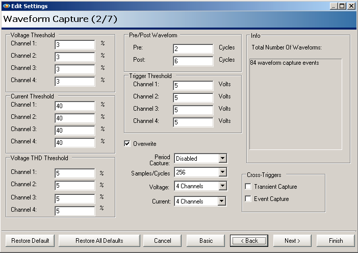
All the other trigger mechanisms work in parallel with the THD trigger, so multiple trigger types may be active at the same time, or disabled. Entering a value of zero will disable THD triggering for a channel.
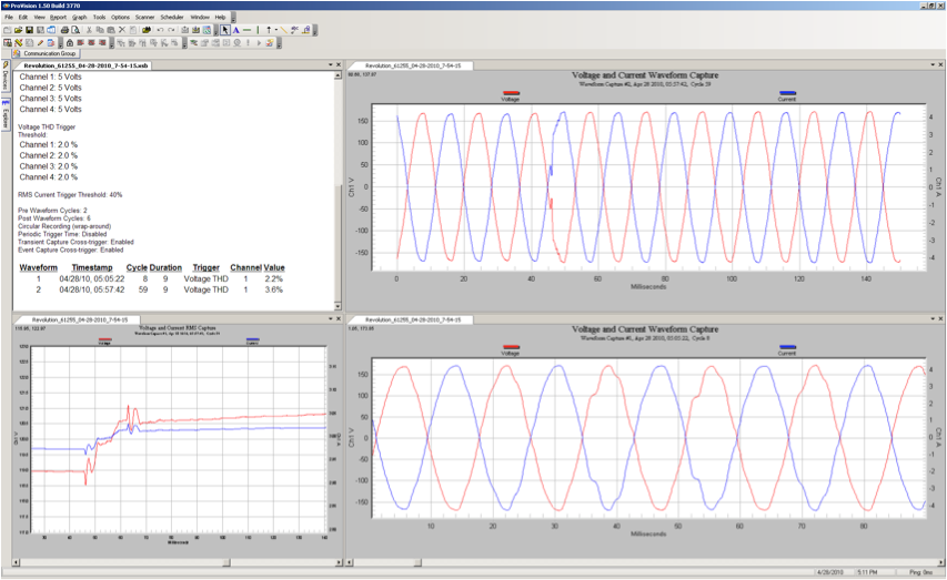
Figure 2 shows a waveform captured with the new THD trigger mechanism. The disturbance near zero-crossing only produced a small RMS voltage change (a couple of volts, as seen in the RMS trace in the lower left graph), but 2.2% THD change.
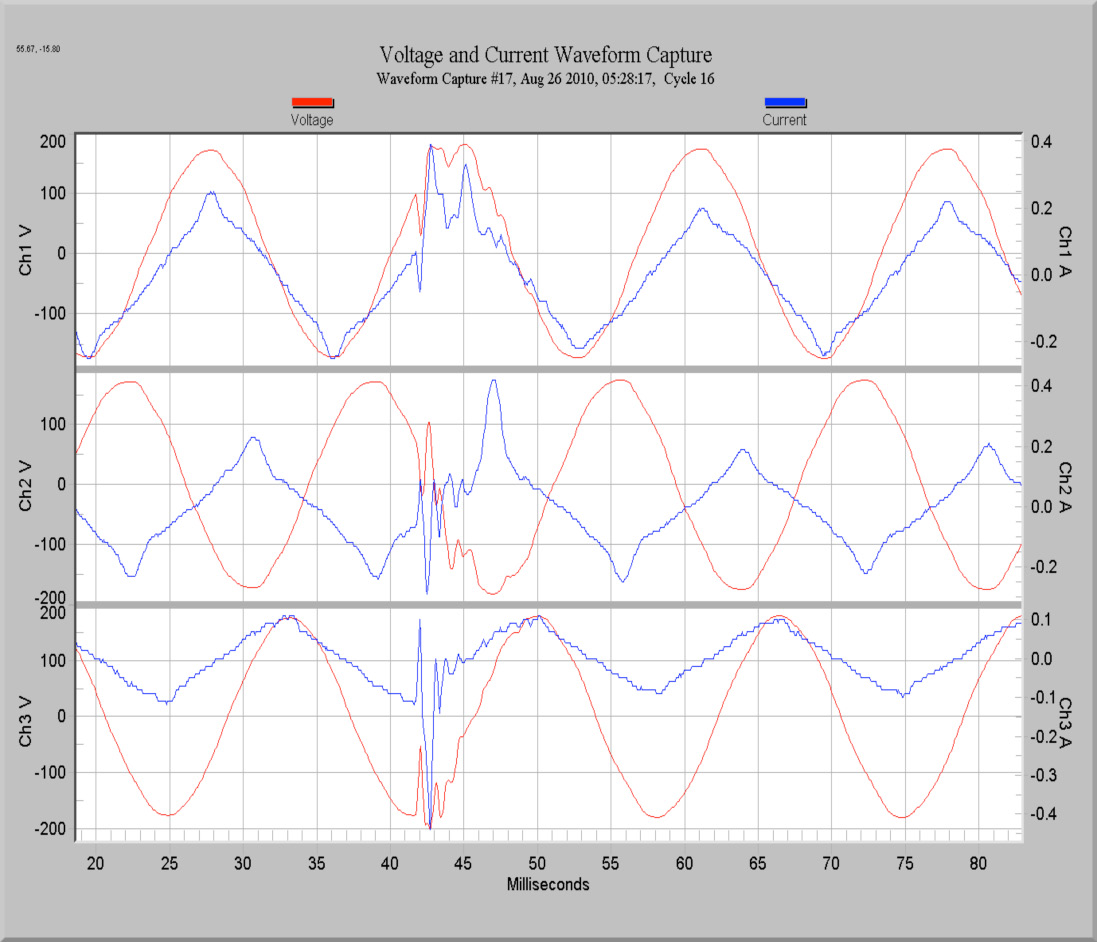
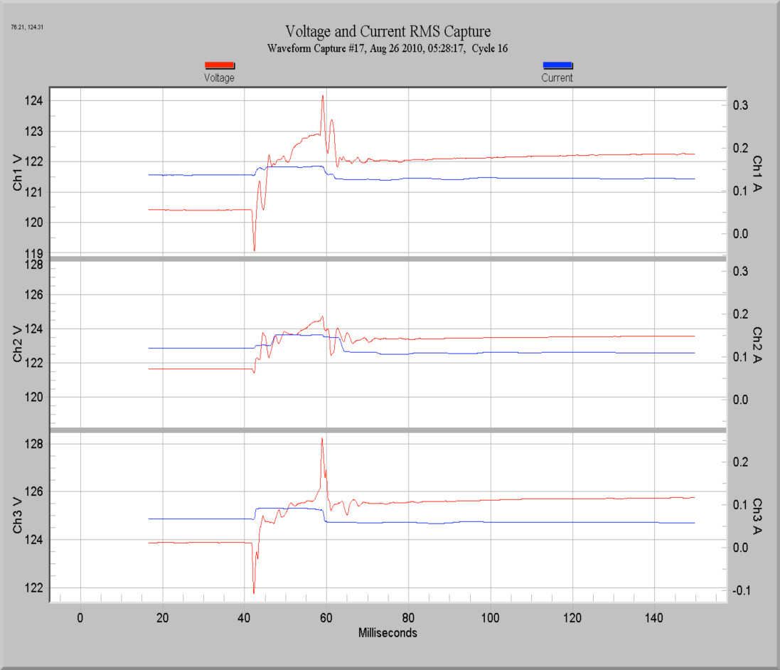
A much more severe example can be seen in the next capture. Here, the THD changed by 9.9% from one cycle to the next, a fairly large change. Despite the severe waveform distortion, the RMS values didn’t actually change much during the event – the maximum change was under 5 Volts. Setting a magnitude-based threshold tight enough to capture an event like this would create many false triggers, but the THD trigger metric easily captures the event, without the risk of false triggers on non-events.
Two other new trigger mechanisms have been added, in addition to THD triggering. It’s now possible to trigger a waveform capture based on other triggered record types. For example, a transient capture or event capture can also trigger a waveform snapshot. Once triggered, a waveform capture generated from these other events produces the same length and type of waveform record as other waveform events.
The setup for these cross triggers is in the Waveform Capture setup screen. Simply enable cross triggering for transient or event capture, and a waveform capture will be triggered at the same time.
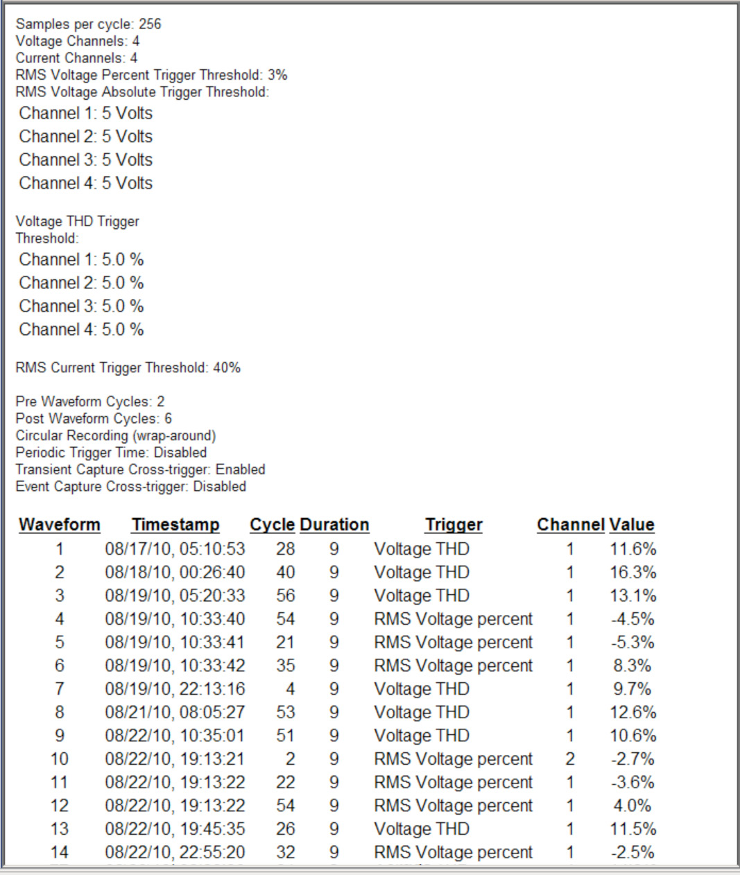
To help sort out all the possible triggers for waveform capture events, a new section to the waveform capture report has been added. The trigger source for each waveform capture is now listed. The example shown is from the same recording as the previous example. The waveform capture settings are displayed in the report header, and for each waveform capture, the Trigger source and magnitude are listed. This report is accessed in ProVision by choosing Report, List of Waveforms from the main menu.