
Abstract
The PMI mounting bracket provides a variety of methods to temporarily or permanently attach a Revolution or 3-phase Boomerang to a metal enclosure, mounting plate, or many other points. Internal magnets allow for quick attachment and removal inside a panel or transformer enclosure while various screw and strap features are included for more permanent situations. For maximum flexibility, the recorder may also be removed without removing the bracket. We’ll go into all of these options in this whitepaper.
Bracket Design
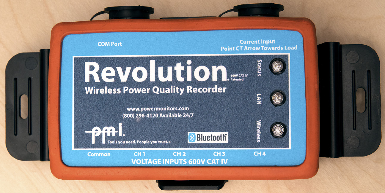
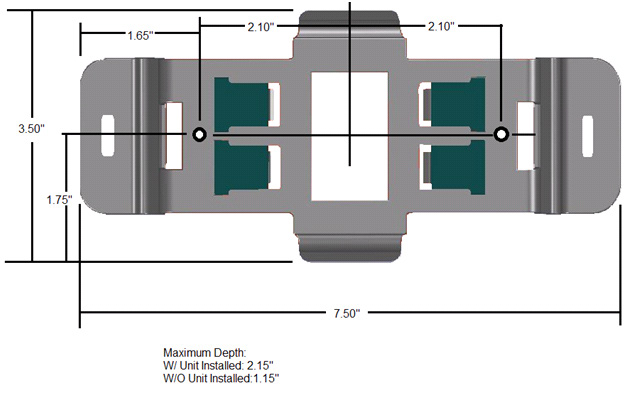
The mounting bracket (Figure 1) is constructed of an ABS/polycarbonate blended plastic, specially designed to be flame retardant and provide a safe, reliable means of securing a power quality recorder, such as the Revolution (see Figure 2). The bracket meets the highest UL standard for flammability resistance and is suitable for indoor or outdoor locations. The mounting bracket itself measures 7.50″ X 3.50″ X 2.15″.
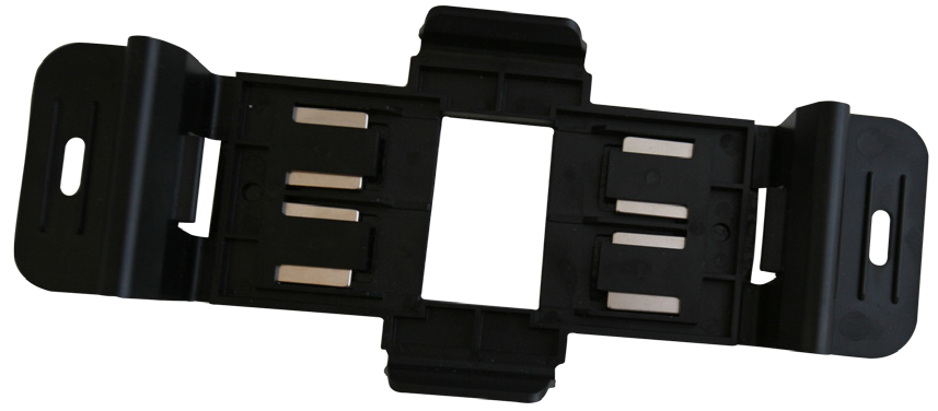
Four high-strength rare earth magnets are embedded in the bracket for attachment to a metallic wall or enclosure. These magnets are removable.
The center opening provides a means to view the device serial number and modem ESN without removing the bracket. The back of the bracket is covered with a slip-resistant material to help the unit stay in place when magnetically attached to a vertical surface.
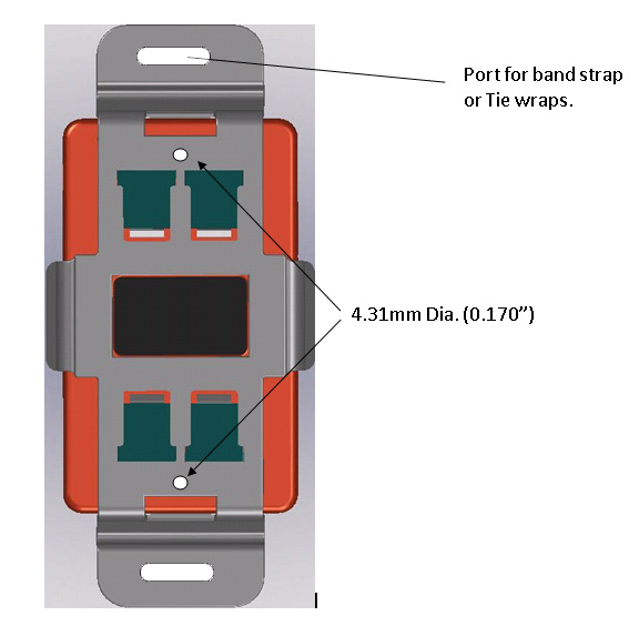
A dimensioned drawing of the bracket is shown in Figure 3, and mounting features are shown in Figure 4.
To attach the bracket to the Revolution or 3-phase Boomerang housing (Figure 5), snap the two tabs on the bracket into the two slots on the housing. Ensure that the device is fully snapped into the bracket. To remove the device, press the two ends of the bracket away from the device (thus disengaging the bracket tabs), and pull the device away from the bracket. The Revolution or Boomerang may be removed from the bracket while the bracket remains attached to the wall or panel. Typically for temporary mounting, the bracket remains clipped to the Revolution and essentially is an extension of the Revolution housing. In a permanent mount, the bracket is installed on a wooden or metal plate or another surface with screws, and a Revolution or Boomerang is attached to the bracket as needed.
Magnetic Mounting
The four rare-earth magnets allow the bracket (with Revolution) to be attached to a ferrous metallic surface. The total weight of a Revolution Unit with Flex CT and voltage leads attached is about 2.5 lbs. The included magnets can hold up to 5 lbs. of weight in suspension (overhead hanging; pulling perpendicular to a horizontal metallic surface). The bracket can support up to 10 lbs. before it begins to slip vertically (if the bracket is mounted flush to a vertical metallic surface). This method prevents the weight of the recorder from being applied to the voltage or CT leads. Normally each CT will be supported by the conductor it’s clamped around, and the bracket will support the weight of the Revolution, the voltage leads, and a portion of the CT wiring.
The non-slip surface on the back of the bracket is important in maintaining the overall grip strength. This surface should be relatively clean and intact when the bracket is installed.
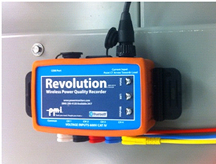
To use the bracket, first clip it to the Revolution or Boomerang, then stick the assembly to the ferrous metal wall or plate (Figure 6). It’s easily moved in case an adjustment needs to be made for cable routing, etc.
Do not place the bracket in a position such that if the magnets slip; the Revolution may fall on to energized conductors, especially conductors with voltage over 600V, as the Revolution’s insulation is not rated for such voltages.
Screw Mounting
Screw mounting holes are provided for a more permanent bracket installation. There are two screw holes, 0.17″ in diameter, that can accept 5/32″ screws or smaller. This is a good mounting choice if you need to mount to a wooden or sheet-metal plate. The screw holes are recessed, so flat-head screws are not required. Before screwing the bracket in place, make sure the location is close enough to the voltage and current sources so that the voltage leads and CTs will be long enough to reach. Also, do not mount the bracket in a location where, if the screws fail, the Revolution could fall into contact with energized conductors, especially those with voltage over 600V.
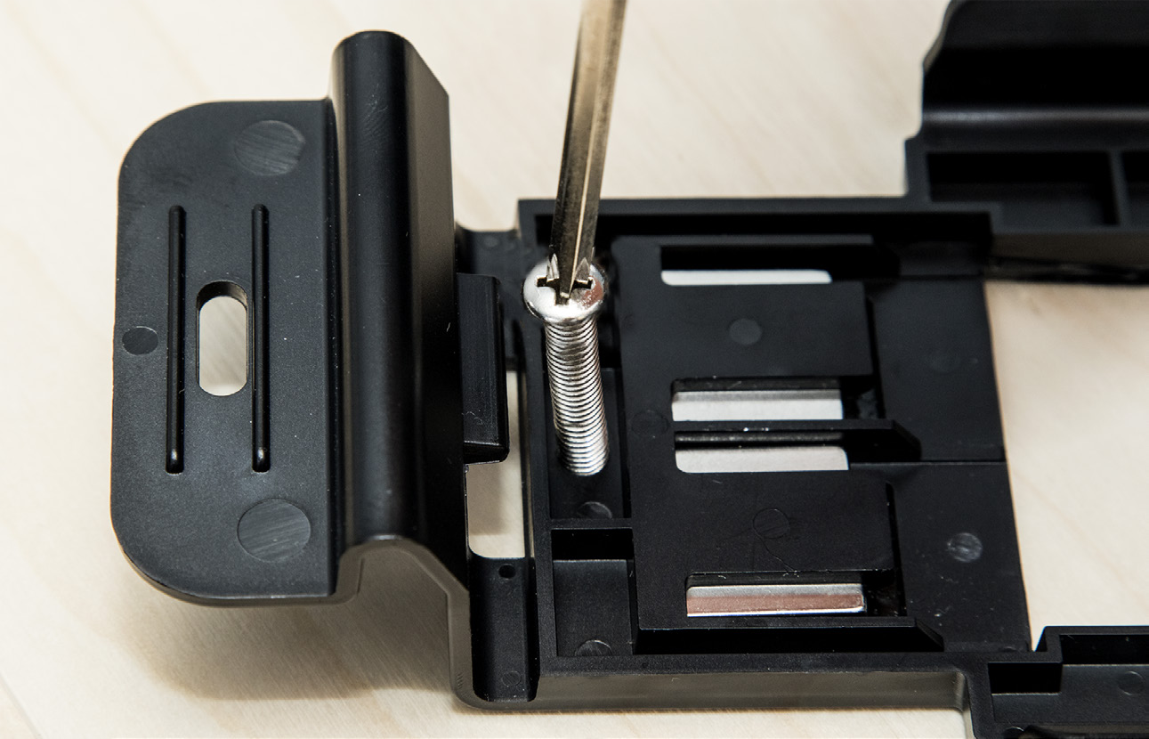
To use the bracket with screws, first determine a location for the bracket that takes into account the lengths of the leads and other attachments. If needed, drill pilot holes into the surface that will hold the bracket. Place the bracket and drive the screws to mount it (Figure 7). Self-drilling, and/or self-tapping screws, or small nuts and bolts may be used. Once the bracket is in place, snap the Revolution or Boomerang onto the bracket.
Strap Mounting
The end tabs of the bracket contain two cutouts that can be used to either zip tie or band the bracket/unit in place. You can use zip ties to fasten the bracket to conduit or other small diameter fixtures near where the unit will be placed.
If you are using zip ties to fasten the bracket, please be aware that too much force applied to the end tabs may bend the tabs out far enough to release the unit from the bracket. Do not deform these tabs such that their tabs are not fully seated in the Revolution housing slots.
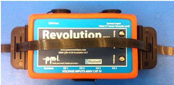
If you need to fasten the bracket to a larger object, a binding strap (preferably nonconductive) may be threaded through both slots to secure the unit (Figure 8). Alternatively, a band or cord may be looped through one slot. Suspending the bracket and Revolution with a cord from a single slot prevents the Revolution weight from pulling on the voltage and CT leads, but does not provide a secure attachment for the Revolution itself.
Conclusion
The mounting bracket is a versatile accessory for installing a Revolution or 3-phase Boomerang in a variety of locations. Whether using magnets, screws, or a strap, the bracket provides a secure attachment while preserving the unique small size of Revolution and Boomerang.