
Abstract
Clamp-Style Current Transformers (CTs) are a convenient and safe way to measure current flowing through a conductor. PMI offers the TLAR line of iron core CT clamps in both the TLAR and TLAR-S form factor. Both clamp styles have the same user-selectable current ranges when deployed in the field with a recorder: 20A and 200A.
What is a Current Transformer?
Current transformers allow users to read current in an AC system safely without having the measuring device be part of the circuit. This is accomplished thanks to the main components of a current transformer – the primary winding, secondary winding, the magnetic core, and a burden resistor. A visualization of these components can be seen in Figure 1.
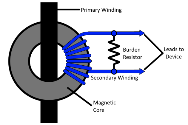
The primary winding, which is generally the individual conductor you wish to measure current on, goes through the magnetic core of the transformer. The secondary winding wraps around the magnetic core of the CT many times to step the measured current down to a usable level. Commonly used current transformers are of two different core types: solid-core and split-core. Solid core transformers require you to unhook a conductor to pass it through the core of the transformer for install. These are typically used in new installations as there is no concern of the load being down while the CT’s installation occurs. Split core, as the name suggests, has the core split into two pieces. This allows the core to be opened so that it can be installed around live conductors in the field with no worry about taking a load offline for install. All of PMI’s TLAR Current clamps are of the split-core type, allowing one to easily install them where-ever and when-ever they like.
Traditional current transformers can produce dangerous overvoltage conditions on the secondary winding, if the correct conditions are met. This is because as current flows through the primary winding’s conductor, a magnetic field is produced that creates a magnetic flux in the core of the transformer. This flux induces a voltage onto the secondary winding, allowing current to flow in the secondary winding’s circuit and is proportional to the primary winding’s current. In use, the current transformer will attempt to develop the required voltage to force the secondary current through the circuit – if this were an open circuit, theoretically infinite voltage would be generated. If a high voltage condition is induced on the secondary circuit, this results in a shock hazard for the user. The Burden Resistor prevents this from occurring by inducing a load on the secondary winding while not saturating the CT’s core. PMI’s TLAR CTs utilize this resistor as well as other suppression devices to ensure a safe working environment for the end-user.
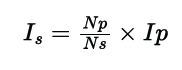
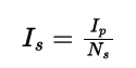
The output current of the secondary circuit can be determined by the formula in Figure 2. Where Is is the secondary current, Np is the primary circuit windings (typically 1), Ns is the secondary circuit windings, and Ip is the primary circuit current. If only one primary winding is utilized, the formula can be simplified as shown in Figure 3. When looking at current transformers, you will generally see their maximum currents expressed as a ratio, say, 200:5. This ratio indicates that if 200 amps are flowing on the primary winding, then 5 amps will flow on the secondary winding. This translates to a 40:1 ratio, meaning that for a single primary turn, there are 40 secondary turns. A secondary current of 5 amps for metering in the utility industry is very common, with PMI’s TLAR clamps being perfect for reading the secondary current of a metering CT.
PMI’S TLAR CT CLAMPS
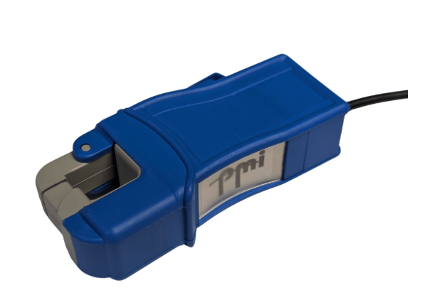
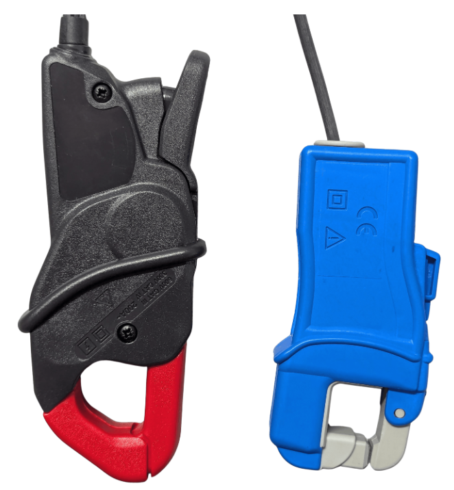
PMI’s TLAR clamps are all split iron-core current transformers which allows the TLAR to be installed on pre-existing conductors. Two different sizes of CT clamps are available from PMI – the TLAR and TLAR-S. Both sizes of TLARs utilize an opening jaw that is easily operated with one hand, allowing for simple installation in the field. The TLAR clamps, shown in Figure 4, are red/black in color and can fit a 4/0 AWG aluminum direct burial cable between the jaws. In contrast, the TLAR-S clamps are smaller, blue/gray in color, and are more compact as seen in Figure 5. The TLAR-S’ smaller stature allows them to fit in tighter spaces better – Figure 6 shows a size comparison between the two clamp types. The standard TLAR and TLAR-S clamps come in 2-, 3-, and 4-Channel f lavors that are compatible with Revolutions, 3-Phase Boomerangs, Ethernet Boomerangs, and Seekers. With these TLAR sets, it is possible to have a channel difference between a recorder and a current clamp setup. If there are more channels in the clamp set than the recorder has or is set to record, the extra channels are ignored. However, if the clamp has less channels than the recorder is set up to record, the missing channels will report as zeroes in the recording.

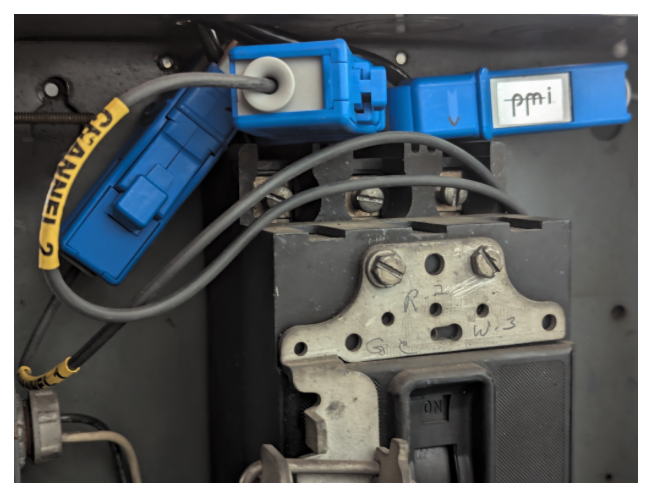
The Bolt compatible TLAR/TLAR-S clamps are only available as a 3-Channel setup. It is worth noting that the Bolt clamps are not compatible with PMI’s older products. Taking a look at Figure 7 shows a set of Bolt TLAR-S clamps installed on the feeds of a motor starter in a close-clearance cabinet.
All the TLAR clamps that PMI offers are suitable for lower range current measurements, with user-adjustable ranges of 20A or 200A full-scale. When attempting to monitor low current applications, such as secondary monitoring of a 5A metering CT, the user-selectable 20A range is well suited for this task. In comparison, PMI’s Flex Current Transformers, or Flex CTs, can exhibit reduced accuracy when attempting to read very low currents when compared to PMI’s Iron-core TLAR clamps. The Flex CTs are also a bit more conductor-position sensitive than the TLARs due to their internal construction. However, the TLAR Clamp’s rigid body construction makes it a little harder to fit the clamps in odd-shaped or sized spaces where the Flex CTs can comply with these odd-shapes to fit better. Sustained severe over-current can also cause the TLAR clamps to overheat and cause damage to themselves.
Tips for using PMI’s TLAR Clamps
- TLAR Clamps are designed to be used when the clamp jaws are completely closed. If there is a small gap between the jaws, it will create inaccuracies in the recording. This will also result in the clamps emitting a buzzing sound. If this buzzing is heard, double check the clamp jaws are fully seated. Opening the jaws, wiping them off, and reinstalling is recommended to ensure no debris is on the jaw surfaces.
- The clamp body should not be placed against high current conductors. If high-current conductors are close to the clamps, they can magnetically couple and result in inaccurate readings being sent to your recorder.
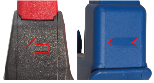
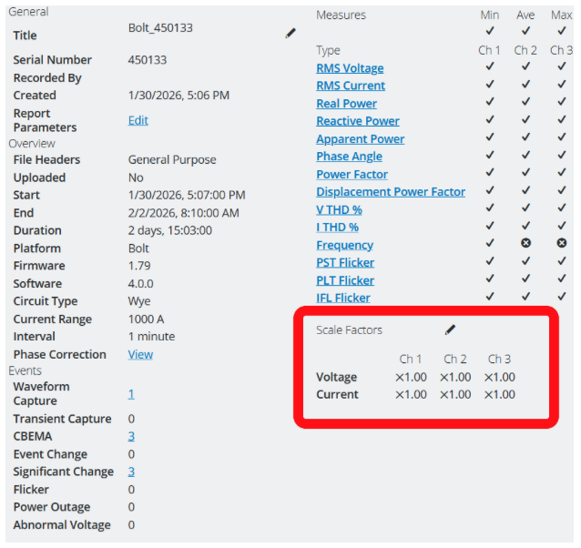
- Each TLAR clamp has a small arrow on the body to indicate the current flow direction – these can be seen on both the TLAR and TLAR-S Clamps in Figure 8. The arrow should be pointing towards the load when installed. If the clamp is reversed, the current will be reported as 180° out of phase. If it is found that a clamp was reversed in a recording, you can use a scaling factor of -1 in ProVision or PQ Canvass to help analyze the recording. Reference white paper “Using Scale Factors for PT/CT Ratios and Per-Unit Analysis in ProVision” to learn more about setting up scaling factors in ProVision. For custom scale factors in PQ Canvass, white paper “Using PQ Canvass” shows how a user can apply a scale factor to the 1-second RMS streaming internal data that is sent into PQ Canvass. If a user wishes to apply custom scale factors to a recording in PQ Canvass, this can be done by editing it at the recording Header Report, highlighted in Figure 9.
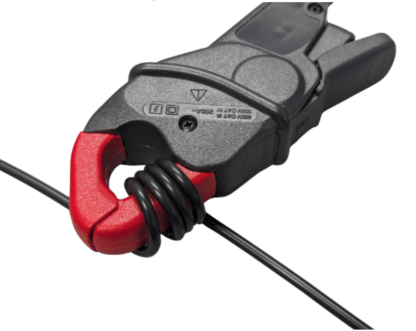
- If you are reading a very low current, you can wrap the conductor you are measuring current on around the clamp for an increase in resolution. If you wrap the primary conductor around the clamp jaw, adjust your scale factors in ProVision or PQ Canvass based on how many times the conductor was wrapped. For instance, if you are wrapping the conductor around the jaws four times like is seen in Figure 10, you would input a 0.25x scale factor. This is helpful as when TLARs are used on 5A CT Secondaries, the nominal can be well under the 5A max output of the CT. If the monitored current is on average under 1A, wrapping the conductor around the clamp jaws multiple times is beneficial for better readings. It is beneficial to ensure the recorder is set to the 20A current range to ensure the best recording resolution is utilized.
Conclusion
PMI’s TLAR Current Transformers are designed for measuring lower-current loads accurately. They are also available in multiple configurations and sizes to ensure most all of your deployment needs are met. Key takeaways for making use easier are to ensure that the TLAR clamp arrows are pointing towards the load, keep the clamp’s jaw surfaces clean and closed during use, and to utilize scale factor adjustments when viewing your recording if you have a clamp installed backwards, or are wrapping the conductor you are measuring around the jaw multiple times to obtain a higher data resolution.