
Abstract
There are a large combination of meter forms for single and poly-phase socket recorders. Understanding the different form factors can be challenging when choosing a meter base specific socket recorder. This document explains each form factor offered and the corresponding socket recorder required for the associated service.
Meter Base Types
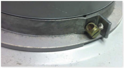
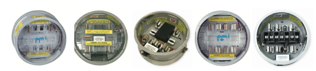
Tab Style: Tab style meter bases require the use of special hardware called tabs. Tabs are used to fasten the recorder to the meter base when the lid will not go over the socket recorder. The tabs are secured by screw adjustments as shown in Figure 1 below.
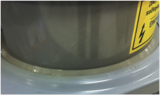
Without Tab: Newer style meter bases do not require a special locking tab to hold the socket recorder in place. The lid of the meter base goes over the socket recorder and is secured when closed. The socket recorder is secured in the meter base as shown in Figure 2.
Single Phase Form Factors
Meter bases are offered in different wiring configurations and are determined by the industry standard “form factor.” Each meter base form is designed to be used in a specific application for the required service type.
There are different forms for single phase and polyphase services, and different forms for wye and delta connections. In some cases, the forms are different in ways that affect a revenue meter, but not a PMI recorder – e.g. 120V vs. 277V nominal, or 5A vs 200A current levels. Some forms differ only in blade arrangement, or in number of channels available for measurement.
PMI offers several variants of the socket recorder to cover the most common meter base forms. Because of the commonality in many forms, only a few different models are required, but it’s important to understand the differences to ensure that the correct recorder is selected. The tables that follow describe the form factors offered by PMI.
| Form | Description | # of Blades | Voltage and Current Connections | INPUTS Measured | 600V Rated |
|---|---|---|---|---|---|
| 2S | Single phase, 3 wire, 120/240V | 4 | Center-tapped 240 (DT) w/Neutral | 1-N, 2-N (120V) | NO |
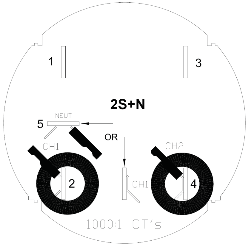
| 2S+N | Single phase, 3 wire, 120/240V | 5 | Center-tapped 240 (DT) w/Neutral | 1-N, 2-N (120V) | YES |
Poly Phase – Directly Connected (1000:1 CT’s)
| Form | Description | # of Blades | Voltage and Current Connections | INPUTS Measured | 600V Rated |
|---|---|---|---|---|---|
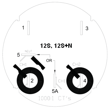
| 12S+N | Three wire network (2 phases), 120/208V | 5 | P1-N (120V), P2-N (120V) | 1-N, 2-N (120V) | YES |
| 12S | 3 Phase 3 Wire Delta (no neutral) | 5 | Three V phases > No Neutral; 1-2, 3-2 (120/240/480V L-L) | 1-2, 3-2; 120, 240, or 480V L-L | YES |
| 14S, 16S | 3 Phase 4 Wire Wye, 120/208V or 277/480V | 7 | Three V phases direct & Neutral; 1-N, 2-N, 3-N (120 or 277V) | 1-N, 2-N, 3-N (120 or 277V) | YES |
| 16S | 3 Phase 4 Wire Delta | 7 | Three V phases direct & Neutral, 1-N, 2-N (120V), 3-N (240V) | 1-N, 2-N (120V), 3-N (240V) | YES |
| 15S | 3 Phase 4 Wire Delta, 240V L-L, 208V 3-N, 120V 1 and 2-N | 7 | Three V phases and Neutral, 1-N and 2-N (120V), 3-N (208V) 3 CT currents |
Metering Poly Phase – Indirectly Connected through PT’s/CT’s (100:1 CT’s)
| Form | Description | # of Blades | Voltage and Current Connections | INPUTS Measured | 600V Rated |
|---|---|---|---|---|---|
| 6S | 3 Phase 4 Wire Wye 120/208V or 277/480V, with 3 CT’s | 13 | Phase 1 and 3 direct; 1-N, 3-N (120 or 277V); 3 CT currents | 1-N, 3-N (120 or 277V); 3 CT currents | YES |
| 6S | 3 Phase 4 Wire Wye 120/208V or 277/480V, with 3 CT’s, and 2 PT’s (120V) | 13 | Phase 1 and 3 through PT’s; 1-N, 3-N (120V); 3 CT currents | 1-N, 3-N (120V); 3 CT currents | YES |
| 8S | 3 Phase 4 Wire Delta, 240V L-L, 208V 3-N, 120V L1 or L2-N, with 3 CT’s | 13 | All three V phases direct; 1-N and 2-N (120V), 3-N (208V); 3 CT currents | 1-N and 2-N (120V), 3-N (208V); 3 CT currents | YES |
| 9S | 3 Phase 4 Wire Delta, 240V L-L, 208V 3-N, 120V L1 or L2-N, with 3 CT’s | 13 | All three V phases direct; 1-N and 2-N (120V), 3-N (208V); 3 CT currents | 1-N and 2-N 120V; 3-N 208V; 3 CT currents | YES |
| 9S | 3 Phase 4 Wire Wye 120/208V or 277/480V, with 3 CT’s | 13 | All three V phases direct; 1, 2, and 3 to N (120 or 277V); 3 CT currents | 1, 2, and 3 to N (120 or 277V); 3 CT currents | YES |
| 9S | 3 Phase 4 Wire Wye 120/208V or 277/480V, with 3 CT’s, and 2 PT’s (120V) | 13 | All three V phases thru PT’s; 1, 2, and 3 to N (120V); 3 CT currents | 1, 2, and 3 to N (120V); 3 CT currents | YES |
| 36S | 3 Phase 4 Wire Wye 120/208V or 277/480V, with 3 CT’s, and 2 PT’s (120V) | 13 | Phase 1 and 3 through PT’s; 1-N, 3-N (120V); Neutral connected to 7th term. block position only; 3 CT currents | 1-N, 2-N (120V); 3 CT currents | YES |
Blade Arrangement
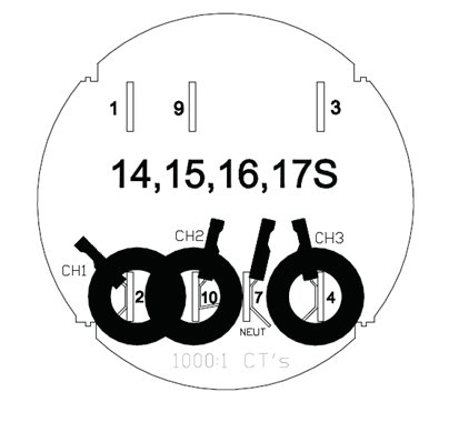
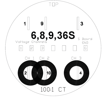
Illustrated below are the blade arrangements and channel assignments as mentioned previously in the form factor tables. The figures below also show the location of the CT’s and their associated turns ratio.
PMI Socket Recorder Part Numbers
| Single Phase | Poly Phase / Metering Poly Phase | ||||
|---|---|---|---|---|---|
| iVS-2SX PLUS | iVS-2SX PLUS N | iVS-3S, opt. 12S | iVS-3S, opt. 14S | iVS-3S, opt. 6S | |
| PMI Part Number | VSS20240251 | VSS20240240 | w/ tabs: VSS30600012 w/o tabs: VSS30600013 | w/ tabs: VSS30600014 w/o tabs: VSS30600017 | w/ tabs: VSS30600022 w/o tabs: VSS30600006 |
| Connection | Direct (1000:1 CT’s) | Indirect through PT’s/CT’s (100:1 CT’s) | |||
| Voltage channels | 2 | 2 | 2 | 3 | 3 |
| Current channels | 2 | 2 | 2 | 3 | 3 |
| CT range | 200A | 200A | 200A | 200A | 25A |
| 600V supply | NO | YES | YES | YES | YES |
| Compatible Meter Forms | 2S | 2S | 12S, 12S Network | 14S, 15S, 16S, 17S | 6S, 8S, 9S, 36S |
| Options | Power, Harmonics | Power, Harmonics | None | None | None |
| Ground Wire | YES | NO | NO | NO | NO |
| Extra Features | NONE | Factory moveable neutral blade to switch between the 6:00 and 9:00 positions | Factory moveable neutral blade to switch between the 6:00 and 9:00 positions | None | None |
The tables above indicate the PMI part numbers for each available form factor. Please note that most socket recorders are compatible with multiple meter base form factors.
With forms 6S and 36S only two voltage channels are typically available – phases A and C are present, but phase B is not. This is a situation where metering PTs are used to step the voltage down to 120V, and only two PTs are installed, to lower costs. In this case, the two-element wye circuit type is automatically chosen by the recorder, and a synthetic B phase is calculated by the recorder to compute power (in the same way the revenue meter would). In this circuit, the phase C voltage appears on channel 2 in the PMI data file. This condition is detected during the two minute countdown by the recorder, and the two-element wye connection automatically used if needed.
Forms 15S and 17S are 3-phase, 4-wire deltas, with a neutral connection. These are handled as wye connections by the recorder, and line-neutral voltages are recorded. Individual phase powers are available, and are meaningful for wye-connected loads. The total power is generated by ProVision, and includes all wye and delta loads.
Conclusion
With all the available service types, choosing the right socket recorder to monitor a PQ issue can be challenging. Familiarizing yourself with the common form factors can help to save you time and money when troubleshooting a system. PMI offers a large selection of commonly used form factors with advanced PQ features that will certainly meet your needs.