Abstract
Recorders connected in ProVision have two primary modes: Standby mode and Ready mode. Each of these modes has a distinct purpose, and some recorder operations in ProVision require the recorder to be in a certain mode. This whitepaper serves as an overview and explanation of these two recorder modes.
Identifying Modes
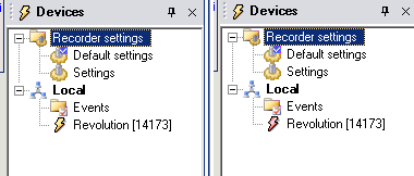
To determine the mode a recorder is in, connect the recorder in ProVision. This will cause the recorder to be registered and displayed in the Explorer Tree. The color of the “lightning bolt” icon indicates which mode the recorder is in as shown in Figure 1. For recorders in Ready mode, the icon appears yellow. For recorders in Standby mode, the icon appears red.
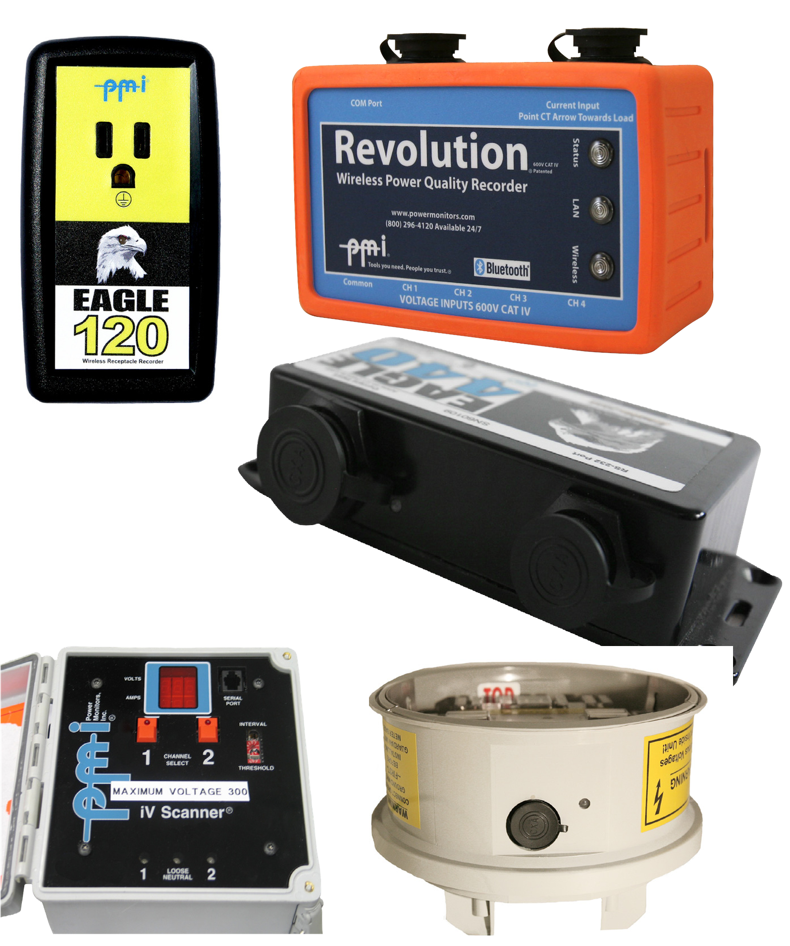
The recorder itself also displays its mode accordingly. Most PMI recorders have an LED indicative of their state (Figure 2). For recorders in Standby mode, this LED is always on. However, Ready mode is displayed in different ways depending on the recorder, as shown in Table 1.
| Recorder | Ready Mode | Standby Mode |
|---|---|---|
| Revolution | STATUS LED flashes green every six seconds | STATUS LED is solid |
| Eagle Series, Eagle 120 | LED flashes green every six seconds | LED is solid |
| Socket Recorders | LED flashes red every six seconds | LED is solid |
| VIP | LCD display is any message except “Charging Battery” or “Comm mode” | LCD display message is either “Charging battery” or “Comm mode” |
| iVS600 | Red LED on channel 1 button is not lit | Red LED on channel 1 button is lit |
Ready Mode
Ready mode is primarily used by recorders that are ready to be deployed to record power quality data, or for recorders connected in ProVision currently displaying real-time data. Whenever recorder operations are completed and the recorder is ready to be disconnected and deployed, it should be set to Ready mode. During Ready mode, the recorder is actively making measurements.
Standby Mode
Standby mode is for recorders currently connected to ProVision in which a recorder operation is in progress that involves configuration or downloading of data. When a recorder is in Standby mode, no power quality data is being recorded. Being in Standby mode is necessary when initializing a recorder with new settings, when retrieving a recording file from a recorder, or when upgrading the firmware on a recorder.
For the cleanest ending of a recording, put the recorder into Standby mode before disconnecting it. Since no measurements are being made while in Standby mode, this prevents the process of physically disconnecting the recorder from its source as being registered as an event. For example, removing the voltage or current connections could be recorded as a PQ event if recording is still occurring.
Changing Modes
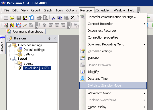
To change the mode of a recorder, select the desired recorder with the right mouse button. Doing so will open a context menu. The entry fourth from the bottom, directly above the last separator bar, allows for the mode to be changed as shown in Figure 3. Note that this menu entry is contextually dependent on the current mode of the recorder: for recorders in Ready mode, it will display a prompt for “Switch to Standby Mode”, and for recorders in Standby mode, it will display a prompt for “Switch to Ready Mode”. Not all recorders support Ready mode with a cable connected. Generally, all USB, Ethernet, and cell recorders do, along with serial Eagles.
Note that toggling modes is not an instant operation—it may require several seconds for ProVision to verify the connection to the recorder and instruct the recorder to change mode, the process the recorder goes through to actually change its mode, and finally alerting ProVision that the mode change operation has completed.
Some operations in ProVision will cause the recorder to change modes automatically. When this occurs, the requested operation is queued, the mode of the recorder is switched, and then the operation is performed. For example, requesting real-time waveforms from a connected recorder will automatically switch it to Ready mode first, if it’s not already in that mode.
When the recorder is disconnected by selecting the disconnect option for that recorder, ProVision also changes its state to Ready mode. Also, ProVision will disconnect and change to Ready mode any connected recorder when ProVision is exited. Any recorder that loses its connection to ProVision, but was not explicitly disconnected, will remain in Standby mode. However, if a recorder detects voltage on channel 1 while in Standby mode and not connected to ProVision, the recorder will put itself in Ready mode.
Furthermore, some recorders change their modes automatically when certain events occur. For example, Eagles and Revolutions with firmware versions 5.67 and greater will, after prolonged periods of communications inactivity, automatically switch themselves to Ready mode. This is to prevent incidences where if a Bluetooth or cell connection were to drop out, the recorder would not be left in Standby mode indefinitely.
When a recorder is switched to Ready mode, either from an explicit command from the software, or due to an automatic timeout from lack of communication, the recorder will start making measurements (e.g. RMS voltage, current, etc.) and these may be viewed in real time with ProVision. However, the unit may not actually start recording. Recording only resumes if line voltage is detected on input 1. This is to prevent accidental data overwriting in the office. In the field, the unit will be powered from channel 1, and recording will start automatically. If the recorder has just been initialized, the 2 minute countdown will begin, and the recording will start after the end of the countdown.
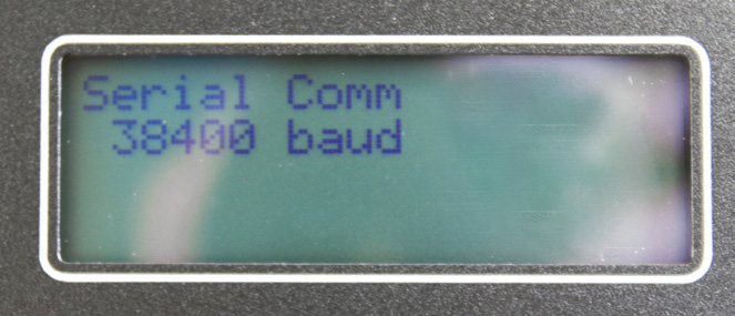
Older iVS-3/600ER box recorders (with the RJ-11 serial cable) automatically go into Standby mode when serial cable is connected to the recorder, even if the other end of the cable is not connected to a PC – these recorders sense the presence of the cable itself. VIP, SVM-10 and iVS-600P box recorders automatically go into Standby mode when the serial cable is connected to the recorder, and the other end is connected to a PC. If powered via the serial cable and not connected to a PC (with no line voltage on channel 1), these recorders will technically be in Ready mode, but not recording. In this case, “Charging Battery” will be displayed on the LCD screen. In Standby mode, “Serial Comm” is displayed on the LCD (Figure 4).
For any recorder with keypad or push-button interface, the keypad or buttons are disabled during Standby mode.
Conclusion
Mode operations are designed to be transparent, so the recorder “does the right thing” automatically, but it is useful to understand what’s happening behind the scenes, and to know that modes can be set explicitly when necessary. The important considerations to keep in mind with the two modes are that Standby mode is used when sending or viewing setup data, or downloading a recording, and Ready mode is used when the recorder should be actively making power quality measurements.