
Abstract
This white paper defines the differences between Real Power, Reactive Power, and Apparent Power in terms used by the power distribution industry. Here the relationships between these different types of power are defined and the basic equations for each are given. The power discussed in this paper is for alternating current (AC) not for direct current (DC), however, the basic definitions are the same. In an AC system, the units of voltage and current used are in RMS.
In physics, power is defined as the amount of energy consumed or produced per unit of time. The unit of power in the MKS system is the watt. One watt is equal to one joule per second. A joule can be defined as the amount work required to move an electric charge of one coulomb through an electrical potential difference of one volt, or one-coulomb volt. Another way of thinking about a joule is that it is the work required to pass an electric current of one ampere through a resistance of one ohm for one second.
Real Power
Real Power (P) is the power that performs work measured in Watts (W). This is the power that is actually absorbed by a totally resistive load and that performs the intended function such as heat, light, or mechanical power (e.g. an electric motor or another type of electromagnetic radiation, both of which are absorbed by the surrounding environment). Again, this is the power delivered into an ideal resistive load and it is completely absorbed, indicating that the current and voltage are in phase (refer to Figure 1). Real power only occurs with a resistive load, and this power delivery and consumption is what the customer is paying for. Attention is given to system design to reduce the reactive component of a power distribution system to a minimum, usually by adding capacitors to offset system inductance, and to keep the voltage and current in phase (Figure 2).
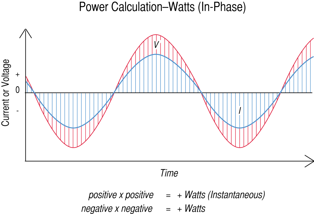
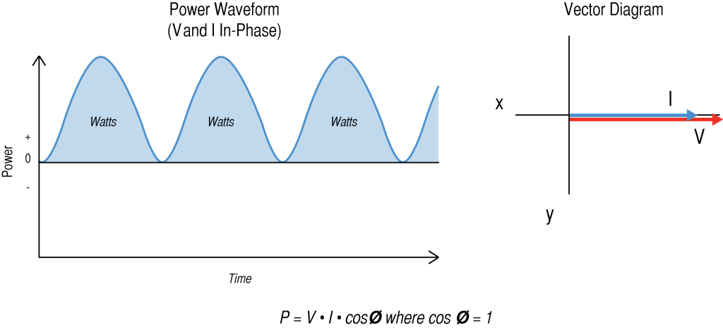
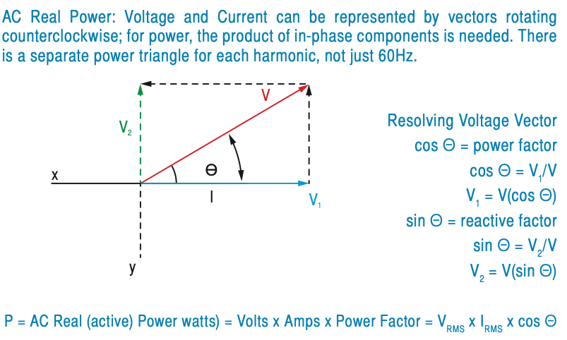
If the load is not purely resistive then the Real Power portion will equal the Voltage RMS times Current RMS multiplied by power factor. Power factor is cosine Θ equals V1 (the adjacent), divided by V (the hypotenuse). If the load is purely resistive, V1 and V will be the same, and the power factor will equal 1. Please refer to Figure 3, resolving the voltage vector.
Reactive Power
Reactive Power (Q) is defined as power flow that does not perform work (sometimes called “wattless power”) measured in Volt Ampere Reactive (VAR). Reactive power is created by a non-resistive load, either inductive or capacitive. Usually the typical load in an electrical distribution system is inductive, due to motor windings and transformers. When reactive power is created by an inductive load, the current lags the voltage by 90 degrees. Thus when reactive power is caused by a capacitive load, the current leads the voltage by 90 degrees. In an inductive load, this power transferred down the distribution system to the inductor, is briefly stored in a magnetic field and then returned back to the utility a short time later. This back-and-forth transfer causes more current flow in the system. In a load that is capacitive, the power is briefly stored in an electrostatic field before being returned back into the system. Either way, whether the load is inductive or capacitive, the current and voltage are thrown out of phase, making reactive power useless. Due to either excessive inductance or capacitance, reactive power is not desired in a distribution system.
In either case (inductive or capacitive system), reactive power is sent through the entire distribution system down to the inductance or capacitance, briefly held in magnetic or electric fields, and then returned back to the system every 60Hz cycle. Although a considerable amount of power can move back and forth, the net real power from this is zero – no useful work is done with reactive power. The current flowing to move reactive power back and forth is real and causes real resistive losses in the wire, increased transformer heating, etc. In effect, it causes higher losses in a power transmission system.
Capacitive and inductive loads can cancel out, leaving a net resistive load, and reducing reactive power flow. This is the purpose of power factor correction capacitors. The waveforms in Figures 4 and 5 show the reason for the losses, a higher current component because reactance has caused the voltage and current to be out of phase.
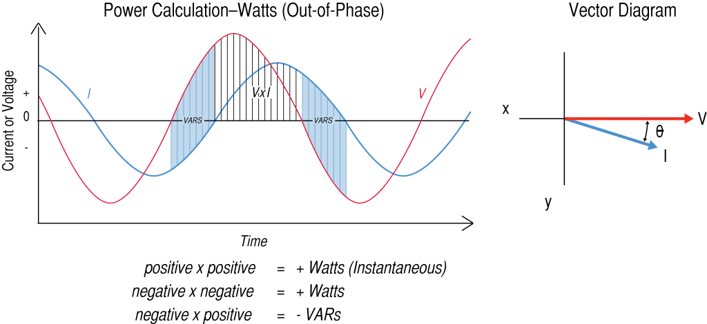
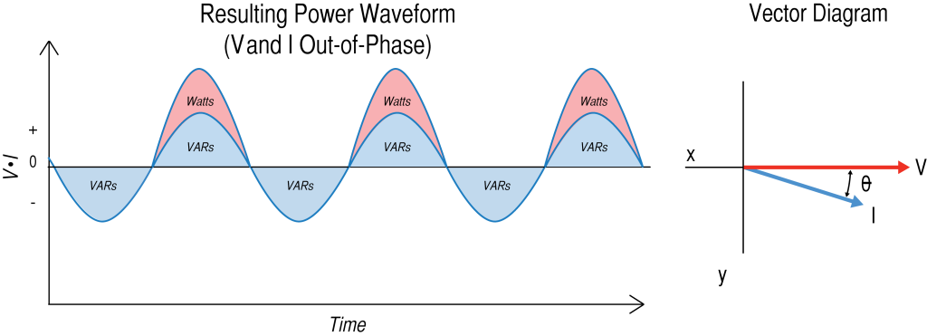
When a reactive load condition exists, the transmission system has to not only support the current required for the resistive load in watts (Volts x Amperes), but also the current required for the reactive load in VARs.
Apparent Power
Apparent Power (|S|) is the magnitude of the complex power measured in volt amps (VA). Apparent Power is the vector sum of the real power and the reactive power combined. In a power distribution system, apparent power is what the system needs to be designed to handle. In the real world, loads are usually not purely linear and resistive; most are a combination of resistive and reactive and are either inductive or capacitive in nature.
Volt-Amps = S = Volts x Amps = VRMS x IRMS
As new loads are added, it is necessary to have test equipment available to be able to quantify exactly what the apparent power is, so the electrical infrastructure can be upgraded to handle the extra load. Sometimes this may be as simple as adding more capacitance in places to allow the voltage and current to be more in phase, by reducing the reactive power caused by higher inductance from typical motor loads.
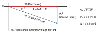
Figure 6 shows the power triangle, the relationship between the Apparent Power (S), Real Power (P) and Reactive Power (Q) and how it relates to the phase angle. Cos Θ is equal to the power factor. This is the angle used to describe the phase shift between the voltage and current. The larger the phase angle, the greater the reactive power that is generated by the system.
Conclusion
Apparent power is a combination of both reactive power and real power. Real power is a result of the resistive component, and the reactive power is a result of capacitive and inductive components. Since reactive power takes away from a system’s total real power handling capability, it must be considered in the design of the power distribution system to ensure that the apparent power output from a system is sufficient to supply the load. It is important to understand these basic AC power concepts in order for the sources and distribution system to meet the requirements to be able to supply the necessary volt-amp power for a given application. As with any system, understanding these specifications and being able to make the proper measurements validate system requirements will ensure success.
Power Monitors Inc. designs and builds different types of test equipment for many power monitoring applications, including real power, apparent power, reactive power and power factor and many others. With these monitors installed in the proper locations, a customer can determine exactly what type of power load the system has. With this information, an operator can make adjustments as needed to optimize power factor by reducing the reactive power, thereby reducing the extra stress and facilitating a longer functional life of the system.