
Abstract
Polyphase power networks are among the most common networks for power transmission. They offer key advantages over single-phase networks. A polyphase system allows the same power to be distributed with less total copper at the same voltage. It also creates an easily predictable rotating magnetic field in a specific direction, reducing motor design complexity. Power transfer is uniform throughout the cycle and hence will lessen vibrations otherwise seen on single phase motors.
A neutral wire allows lower voltage – single phase support on a higher voltage polyphase network. However, in practice, it is not common to run a separate neutral line for transmission. Instead, a neutral line can be created by connecting loads between phases.
The US utilizes three-phase power transmission. Figure 1 demonstrates a simplified three-phase generator. Three distinct windings connected in a delta configuration surround a rotating (US – 60Hz) ferromagnetic core. Each current-carrying conductor is 120° from one another.
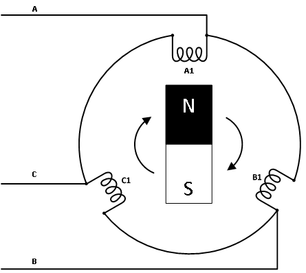
Three Phase Power Measurements
A common misconception performing polyphase power measurements is the requirement to measure each individual line voltage and line current to obtain an accurate power reading. Blondel’s theorem would say otherwise. It states the total power of n number of current-carrying conductors can be accurately measured with n-1 number wattmeters by making a common reference point with one of the conductors.
At first glance this concept is not always intuitive. After all, if we have three-phase power, wouldn’t we need individual power measurements from each conductor? To help further understand how a two-wattmeter solution can be used, we will delve into the theoretical derivation of Blondel’s theorem.
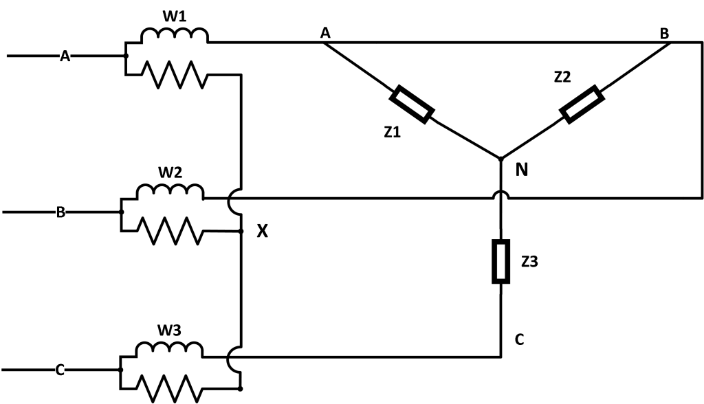
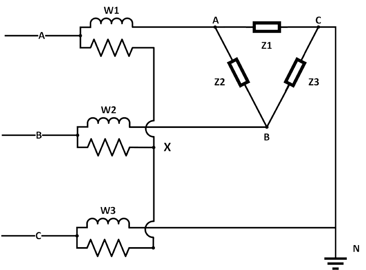
Let’s first consider our intuitive three-wattmeter configuration taken on either a Wye or delta system shown in Figure 2. Our wattmeters are labeled W1, W2, and W3, which comprise an induction coil (for measuring current) and a resistor (for measuring voltage). Each wattmeter connects to an individual phase and to each other at a common point X. Note the X node can be any arbitrary point in space. An artificial corner ground (labeled N for neutral) has been placed for ease of reference on the delta circuit; however, it is not necessary to be grounded.
Since we are dealing with a time varying system (AC power) the average power for the A conductor is expressed by Equation 1. T is the period for all phase voltages; v (voltage) and i (current) are vectors. The white paper, Formulas for Power and Harmonic Measurements, dives deeper into how PMI recorders translate continuous time signals into discrete measurements.
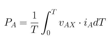
The total power given by the three wattmeters is shown in Equation 2.
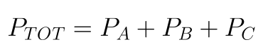
Combining equations 1 and 2, we arrive at Equation 3.

Individual voltages can be broken up into displacement voltages between nodes X and N. Note the N node is shared with the C node on the delta configuration, however, calculations will continue as if they are separate. This allows the calculations to easily translate for Wye configurations with a neutral center tap between the three loads.
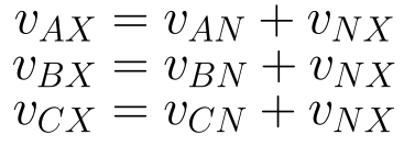
Expanding the above expressions into Equation 3 yields Equation 5.
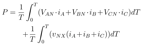
Remembering Kirchhoff’s law of current, the sum of current within a system is equal to zero, shown in Equation 6.

Thus the second integral within Equation 5 reduces to zero, leaving only Equation 7. This is the expression we would expect had the common node X been placed on the neutral node N.

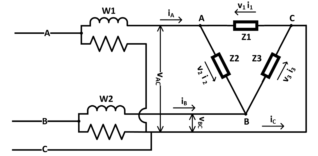
Remember that X can be placed anywhere, even one of the three phase leads A, B, or C. Had X been placed on node C, the third wattmeter would read zero. Thus only requiring wattmeters 1 and 2 to read the total power of the system, as shown in Figure 3.
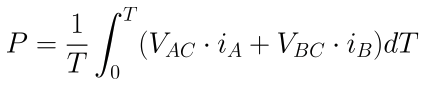
The final expression for total power is represented in Equation 8.
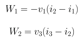
A simple algebraic proof for the two-wattmeter solution is shown below. Using nodal analysis, the power seen at each wattmeter node with equations 9 and 10.
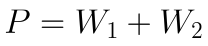
The total power of the three-phase network will be seen as the sum of both wattmeters as shown in equation 11.
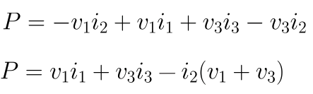
Equation 12 displays the expansion of equation 11 with equation 9 and 10.
Remembering Kirchhoff’s voltage law, equation 14 shows the sum of voltages surrounding a loop is equal to zero.
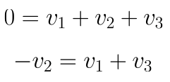
Substituting equation 15 into equation 13, we are left with the final expression shown in 16. As we predicted, the total power of the system is the collective sum of each phase’s power.

Conclusion
A previously written whitepaper, titled Common Mode Input Recorder – Hookup Diagram Walkthrough meticulously details how to wire and initialize a PMI power analyzer for various three-phase and single phase configurations.
The collective average power read by the two wattmeters is the total delivered power distributed across the three connected phases. An intuitive way to understand why this is possible is to recall Kirchhoff’s laws as applied to the delta system. Because the phase-phase voltages around the delta must sum to zero, knowing two voltages is sufficient to reproduce the third. Similarly, the currents must also sum to zero. Thus, three voltage and three current readings gives an overdetermined system due to the delta arrangement, and only two pairs are required for a total power reading.