
Abstract
This white paper describes the sign convention used to represent Power data in PMI Recorders. Most of our recorders offer the ability to record Real Power (W), Reactive Power (VAR), Apparent Power (VA), and Power Factor (PF). In order to fully understand the meaning of these terms, we will first review our Power Quality theory.
Complex Equations
Real Power
PURE Real Power is only consumed when the load is purely resistive (Voltage and Current are purely sinusoidal and in phase with each other). In other words, the product of Voltage and Current are always positive, indicating the direction of energy flow does not reverse. Real Power is the normally expressed in W (Watts) or kW (Watts x 10³ or 1000).
Real Power is computed once per cycle for each pair of voltage and current channels (Sampling rate of 256 samples per cycle).
NOTE: Real Power is signed to indicate the direction of power flow.
Reactive Power
PURE Reactive Power is only consumed when the Current is 90 degrees out of phase with respect to Voltage (not possible in a real power system, but used for theoretical purposes). In other words, the product of Voltage and Current is positive for 1/2 cycle and is negative the other 1/2 cycle, indicating there is no net energy flowing towards the load. Reactive Power is normally expressed in VARs (Volt-Amp-Reactive) or kVARs (VARs x 10³ or 1000).
Reactive Power is computed once per cycle for each pair of voltage and current channels (Sampling rate of 256 samples per cycle for a Harmonic range of 1-51st).

NOTE: Each Vx[k] Iy[k] – Ix[k] Vy[k] term is the Reactive Power contributed by the Harmonic [k].
Apparent Power
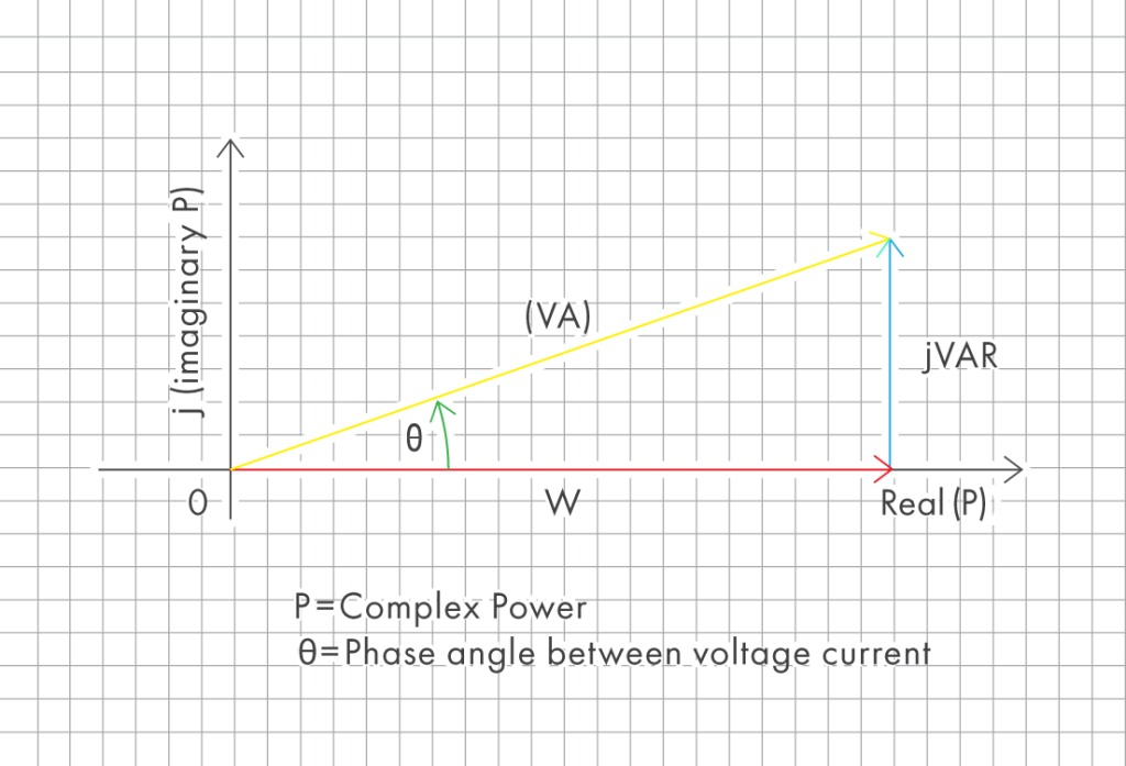
Apparent Power is the vector sum of the Real and Reactive Power (Figure 1). In other words, Apparent Power is the product of the RMS (Root Mean Square) Voltage and Current. Apparent Power is normally expressed in VA (Volt AMPs) or kVA (VA x 10³ or 1000).
Apparent Power is computed once per cycle for each pair of voltage and current channels (Sampling rate of 256 samples per cycle used for RMS calculations).
VA = VRMS × IRMS
NOTE: Apparent Power is an absolute value and has no Sign.
Power Factor
Power Factor is the ratio between Real and Apparent Power in a system. In other words, Power Factor is a practical measure of efficiency in a power system. Power Factor is normally expressed as leading or lagging. Power Factor is computed once per cycle for each pair of voltage and current channels:
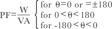
NOTE: This expression is also known as true power factor, since it includes the effects of harmonics.
Now that we fully understand the theory behind the Energy flow in an electrical system, we can discuss the sign convention used in PMI recorders. In a true power system there are many types of loads. There are linear, non-linear, inductive, and capacitive loads just to name a few. Since the electrical power system is so complex, we have to have a sign convention associated with our measurements. When we speak about Real Power, Reactive Power, and Power Factor, we need to be familiar with the sign associated with these expressions.
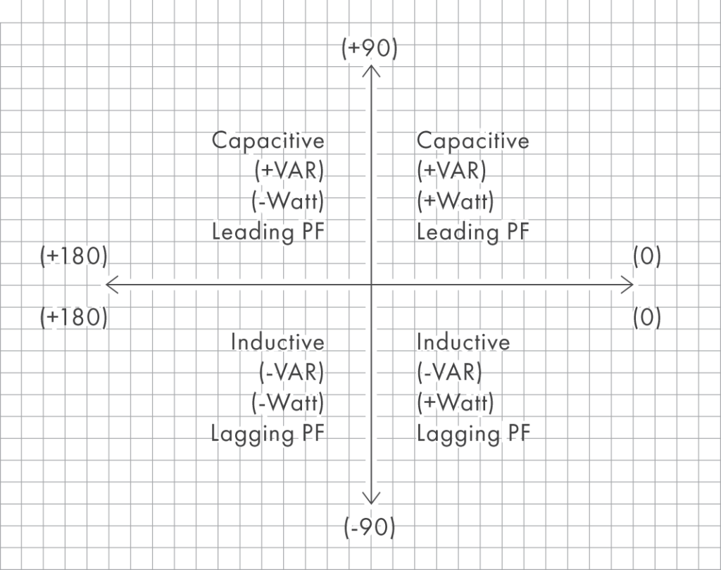
The Sign in the expression is very important because it represents the direction of power flow in the electrical system. Power factor also plays a big role in Power Systems as it represents the quality of power flow. Figure 2 shows common quadrant system used to express angles in mathematical equations. Each quadrant represents an angle due to the phase shift in Current and the leading/lagging Power Factor.
Simplified Sign Convention
Real Power
Negative Watts = Generating Power, Positive Watts = Consuming Power
NOTE: There is always a sign for Watts indicating Power flow direction.
Reactive Power
Negative VARs = Inductive, Positive VARs = Capacitive
NOTE: There is always a sign for VARs indicating Power flow direction.
Apparent Power
Absolute Value from RMS Voltage and Current
NOTE: No Sign
Power Factor
Negative PF = Lagging, Positive PF = Leading
NOTE: There is normally not a sign for PF but +/- indicates lead/lag.
Conclusion
The sign convention used to represent Power Flow in an electrical system is very important for analyzing data. Taking the time to familiarize yourself with the calculations and the sign convention used in PMI recorders is very important. With a little knowledge and understanding in the mathematical representation of Power, you will be able to better understand your Recorded data.