
Abstract
Maintaining acceptable voltage levels along distribution feeders requires careful coordination of voltage regulation equipment and proactive management of reactive power and harmonics. Loads with significant inductive characteristics increase reactive power demand, contributing to elevated feeder current and voltage drop. To mitigate these effects, power factor correction capacitors (PFC) are deployed in both fixed and switched configurations to supply reactive power locally, reducing upstream reactive current flow and maintaining an acceptable steady-state voltage profile along the feeder.
Reactive Power and Voltage Drop
Inductive loads from factories or other commercial buildings draw reactive power from the power grid. When these inductive loads aren’t counterbalanced with capacitors, reactive power must be supplied from further upstream for the inductive loads, increasing feeder current and contributing to steady-state voltage drop. Voltage drop across a distribution line can be approximated by:

Where:
- ΔV is change in Voltage (Voltage Drop).
- R is Resistance.
- IR is Real Current.
- X is Reactance.
- IX is Reactive Current.
Any increase in reactive current (IX) will ultimately lead to an increase in voltage drop, and since reactive current can be locally supplied using relatively simple and cost-effective equipment, power utilities opt to mitigate reactive power demand with banks of power factor correction capacitors.
Reducing reactive power (VAR) allows a system to deliver more real power (W) with the same apparent power (VA) thermal limit of conductors and transformers, since:

Where:
- PF is Power Factor.
- W is Real Power.
- VA is Apparent Power.
- VAR is Reactive Power.
Reducing reactive power demand on a distribution feeder reduces the total RMS current required to supply a given real power load. Lower line current decreases I2R losses, reduces voltage drop along the feeder and frees conductor and transformer thermal capacity for the delivery of additional real power. As a result, the ratio of real power to apparent power increases, yielding an improvement in system power factor.
Power factor correction capacitors supply leading reactive power locally, offsetting the lagging reactive power demand of inductive loads. By providing reactive power closer to the load, capacitor banks reduce the magnitude of reactive current flowing upstream toward the source, thereby lowering overall feeder current and improving system efficiency.
To assure one stays within proper voltage limits, the voltage rise for a given capacitor bank is calculated by:
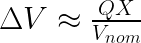
Where:
- ΔV is change in Voltage (Voltage Rise).
- Q is the Reactive Power rating of the capacitor bank.
- X is the Reactance from the source to the bank.
- Vnom is the line-to-line nominal voltage.
PFC Bank Placement
Where you place power factor correction capacitor banks matters as much as why you should place them.
Placing the capacitor bank at the substation reduces the reactive power demand seen by the substation transformer and upstream network, improving overall steady-state conditions on the feeder. This also reduces reactive current flowing through the substation transformer, lowering thermal stress. While this would be beneficial for the substation, the voltage drops downstream from the substation would affect all others on that distribution network.
Ideally, one would place the capacitor bank as close to the inductive load in question as possible. By placing the bank here, it decreases the voltage drop for the installation and those customers on the same branch from the substation.
When capacitor banks are implemented as switched installations, their operation is governed by control schemes that respond to measured system conditions such as feeder voltage, reactive power flow, line current, or predefined time-of-day schedules. These controllers determine when capacitor stages are energized or de-energized to provide reactive power support appropriate to prevailing load conditions.
Under increasing load, feeder current rises and reactive power demand increases, contributing to greater voltage drop along the line due to line impedance. When monitored voltage falls below a defined control setpoint—or when reactive power demand exceeds a programmed threshold—the capacitor bank is switched onto the feeder. By supplying leading reactive power locally, the bank reduces the reactive component of line current, thereby decreasing voltage drop and supporting the feeder voltage profile. Conversely, when load decreases and voltage recovers, the capacitor bank is switched out of service to prevent overvoltage or leading power factor conditions.
Visualizing Capacitor Bank Switching
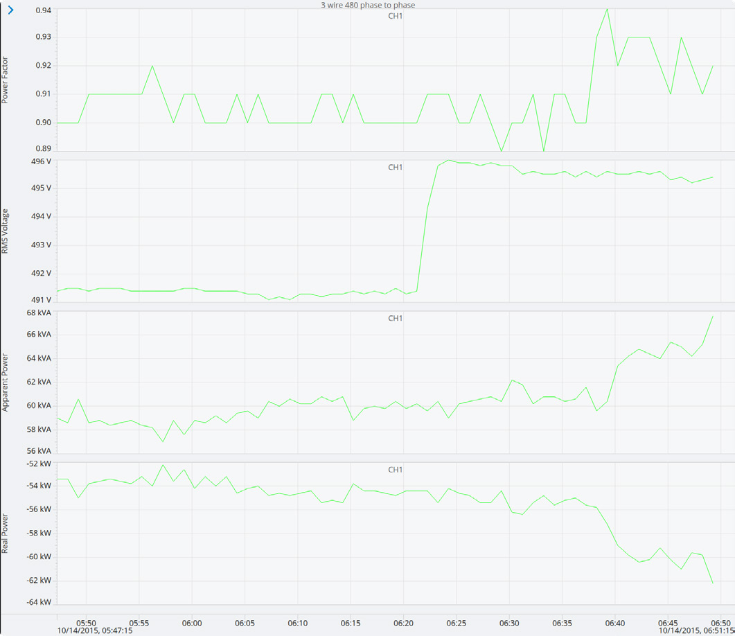
Sudden changes in power factor and reactive power, as well as RMS voltage, indicate a capacitor bank switching on or off. To illustrate this, a PMI Revolution was connected to the system as part of a voltage regulation investigation. Viewing this investigation in PQ Canvass (Figure 1), one sees the clear relationship that power factor, reactive power and RMS voltage have as the capacitor banks are being switched on.
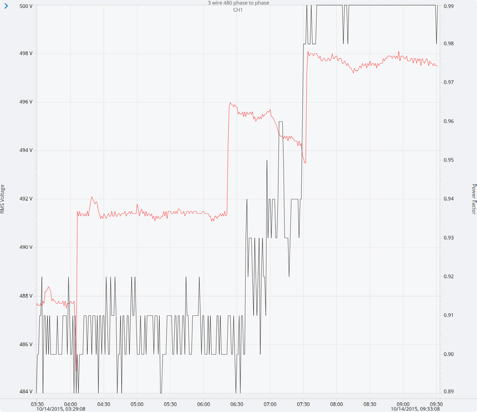
As seen in Figure 2, over the span of 20 minutes the shift in power factor correlates directly with the increase in RMS voltage. This is a clear indicator of how the system’s voltage is responding to changes in reactive power flow across the feeder impedance.
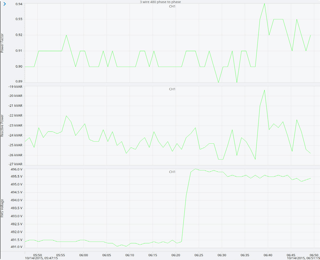
In this recording, power factor changes occur quickly, however RMS voltage steps occurred slower than the changes in power factor. The change in reactive power, however, aligns exactly with the shift in power factor, as power factor reflects changes in reactive power demand at the point of measurement. Viewing the reactive power stripchart can be an equally valuable tool in determining the correlative effects of the user’s PFC banks and steady-state voltage.
Possible Problems
While power factor correction is meant to improve system stability and performance, it can degrade stability and performance as well if proper planning is not exercised. Over correction of the power factor of a system can lead to increased voltages when a light load is detected, causing capacitor banks to switch too easily or too often. This can cause voltage flicker and may increase the wear and tear of voltage regulation systems.
Harmonic resonance can also be a problem, as switching alters the system’s resonant frequency, which may end up amplifying a characteristic harmonic instead of filtering it. This could increase current for a transformer, for example, possibly leading to an overheating failure; capacitor banks themselves may also become overstressed and fail. Using harmonic filters or shifting the resonant frequency away from dominant harmonics helps to prevent amplification of harmful harmonics.
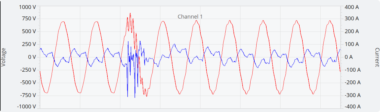
Voltage transients caused by sudden inrush current to the capacitor bank can occur during bank energization, which may cause a sudden dip in voltage followed by an oscillatory “ring”. This will be noticeable in voltage waveforms and sensitive customer equipment, particularly variable frequency drives, may trip or fail. Triggering the capacitor bank switch using controlled point-on-wave switching minimizes the instantaneous potential difference between the source voltage and any residual voltage present on the capacitor at the moment of energization.
Conclusion
To reduce or prevent voltage drops from occurring along a distribution line due to reactive power, power factor correction capacitor banks are utilized. Used in conjunction with other components, like voltage regulators, they provide stability to the power grid from high inductive reactive power demand that could cause a decrease in the delivery capacity of real power downstream. By reducing unnecessary reactive current flow, capacitor banks also reduce conductor losses and transformer loading, decreasing mechanical and thermal stress on distribution equipment.