
Abstract
Transients due to nearby lightning or switching events can cause degradation or failure of almost any electrical equipment. Impulsive transients can pass through transformer interwinding capacitance to appear on the low side without being reduced by the transformer turns ratio. Transients can also cause overvoltage tripping of adjustable-speed drives. Oscillatory transients are generally lower in peak voltage but travel further through a distribution network, and are often present throughout a feeder.
IEEE Std 1159-2019, “Recommended Practice for Monitoring Electric Power Quality”, defines and classifies different categories and subcategories of transients. These categories are described here.
Transients: Impulsive vs. Oscillatory
Transients are defined by IEEE-1159 (2019) as sudden nonpower frequency changes from the nominal voltage or current. They can be conducted or radiated phenomena. IEEE-1159 further classifies transients into two categories reflecting the nature of the polarity of disturbance in the voltage or current waveform. The polarity of impulsive transients is unidirectional (positive or negative) whereas that of oscillatory transients is bidirectional.
Impulsive Transients
- are characterized by their rise and decay times
- may be further classified in IEEE-1159 by rise time into three subcategories
- ns, μs and ms impulsive transients (Table 1)
Rise and decay times are defined by IEEE Std C62.41-1995, “Surge Protection Standards Collection”.
Where described as, for example, a “1.2 / 50 waveshape” this indicates a 1.2 μs rise time and 50 μs decay time. Impulsive transients may also be described using their spectral content and/or duration as appropriate in lieu of rise and decay time.
An impulsive transient is shown in Figure 1. Impulsive transients are quickly damped by resistive circuit elements. There can be significant differences in the characteristics of an impulsive transient at different locations in the system. They are most commonly caused by lightning and might be mitigated by surge suppressors.
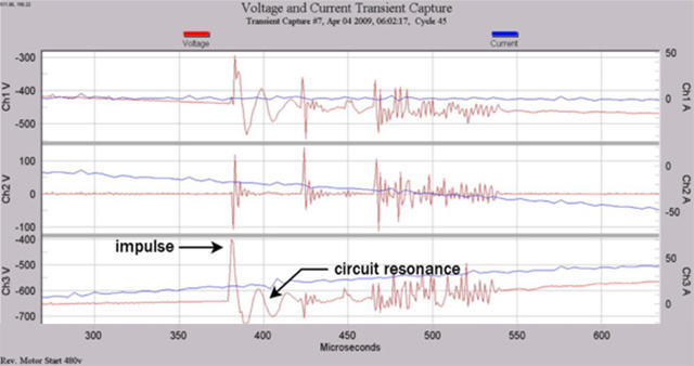
Impulsive transients can also excite circuit resonances to produce oscillatory transients. Figure 2 shows such an excitation.
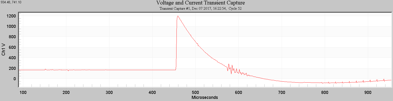
The rise time here would be a measurement of the leading edge of the waveform occurring between approximately 460 and 470 μs. The decay time would be a measurement of the trailing edge of the waveform which occurs here from the peak at approximately 470 μs to a 50% level at around 520 μs.
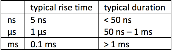
As shown in this table, impulsive transients can include very high frequency spectral content.
The voltage capture on channel 3 of this figure shows an impulsive transient exciting a circuit resonance to produce an oscillatory transient. The impulsive transient has a rise time of a few microseconds and the resulting oscillatory transient has a primary frequency of around 50 kHz.
Oscillatory Transients
- are characterized by magnitude, duration and frequency
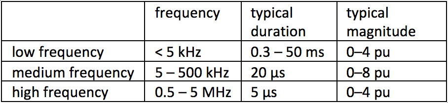
- are further classified in IEEE-1159 by frequency into three sub-categories
- high, medium and low frequency oscillatory transients (Table 2)
Because transients can be measured with the fundamental either included or removed, IEEE-1159 prescribes indicating the magnitude with and without the fundamental when characterizing the transient.
High Frequency Oscillatory Transients
- have a primary frequency > 500 kHz
- typically have a duration in microseconds
High frequency oscillatory transients are almost always caused by switching events such as those related to commutation and RLC snubber circuits. They are also often a response to a local impulsive transient.
Medium Frequency Oscillatory Transients
- have a primary frequency 5 kHz – 500 kHz
- typically have a duration in tens of microseconds
Medium frequency oscillatory transients can be caused by energizing back-to-back capacitor banks where the solution might be pre-insertion resistance or inductance. They can also be caused by cable switching or can be an excitation response to an impulsive transient.
Figure 3 shows a medium frequency oscillatory transient which is the result of excitation by an impulsive transient.
Low Frequency Oscillatory Transients
- have a primary frequency < 5 kHz
- typically have a duration in milliseconds
Capacitor bank energization typically results in a low frequency oscillatory voltage transient of 300 – 900 Hz with a peak magnitude that can approach 2.0 pu but is typically 1.3 – 1.5 pu and durations of 0.5 – 3 cycles of the fundamental. This is a primary cause of low frequency oscillatory transients and solutions for these might be surge suppressors and line reactors.
Low frequency oscillatory transient can also be found with primary frequency < 300 Hz when they are associated with energizing ferroresonance and transformers. This occurs when a resonance amplifies the 2nd or 3rd harmonics of transformer inrush currents or when unusual conditions result in ferroresonance.
These transients could also involve series capacitors.
See Figure 4 for an example of a low frequency oscillatory transient.
IEEE-1159 uses pu (per unit) where 1 pu is the nominal peak value.
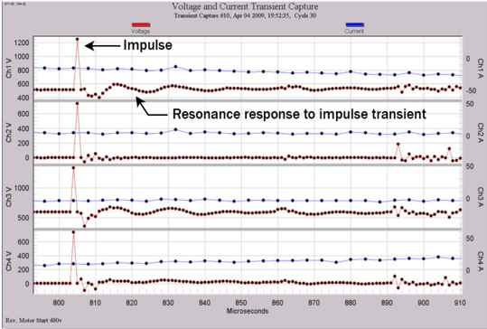
Here an impulsive transient appears on all 4 voltage channels. But Channels 1 and 3 in particular also show a medium frequency resonance response (primary frequency around 75 kHz).
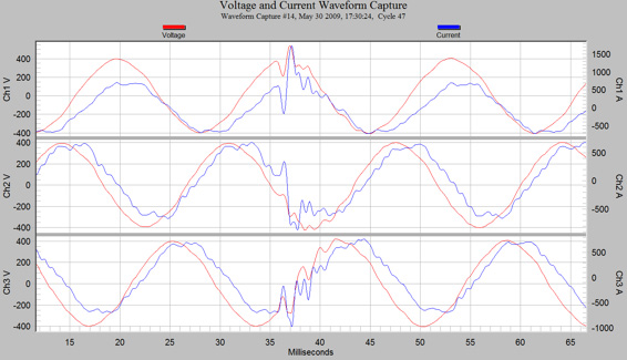
This is a waveform capture with the fundamental included. The low frequency oscillatory transient here appears on all 3 channels. It begins at around 36 milliseconds and lasts around 5 – 10 milliseconds. It has a dominant frequency of roughly 1 kHz.
Conclusion
IEEE-1159 provides definitions and classifications for the categories of transients motivated by their causes and solutions.
Impulsive transients have a disturbance with a unidirectional positive or negative polarity while oscillatory transients have a disturbance with a bidirectional polarity. Both types of transients are further categorized by elements of their waveshapes.
A single disturbance can begin with an impulsive transient which can then excite a resonance to produce an oscillatory transient. This is a common occurrence.
Transients can be measured with the fundamental included or removed, so characterizations that depend on this, such as magnitude, should include this information.