
Abstract
This white paper describes using a motor soft-starter to reduce the effects of line changes due to high current in-rushes on AC induction motors. We’ll start with the basics of induction motors, soft-starters, and culminating with a discussion on how the power quality can be affected and how soft-starters will help counteract these effects. There are several architectures used in these devices, we will primarily compare direct online operation with a typical soft-starter.
What Is an AC Induction Motor?
An induction motor (also called an asynchronous motor) is a brushless motor, often used in industrial applications where high torque is often required. An AC induction motor can operate on single phase or three phase AC power. The induction motor design offers higher reliability without brushes and eliminates the need for periodic maintenance for cleaning / replacement of the brushes.
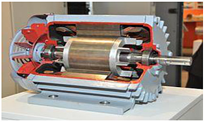
Figure 1 shows a cutaway view for a typical induction style motor. Depending on the type and magnitude of the motor load, induction motors can require a very high inrush current, which can create power quality issues such as voltage sag, poor power factor, and others.
The induction motor works because the electric field moves around the stator coils as each phase of the voltage cycles. This causes the rotor to rotate inside the stator. Since the motor coils are driven off the line voltage, the maximum rotation speed is just below AC frequency.
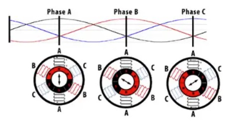
Figure 2 illustrates how each voltage causes the rotation of the rotor. Three phase induction motors are considered “self-starting” since they require no external motor start capacitors or other components to initialize motion.
What Is an AC Motor Soft-Starter?
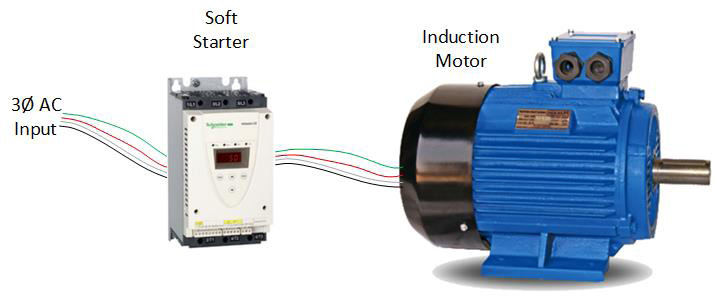
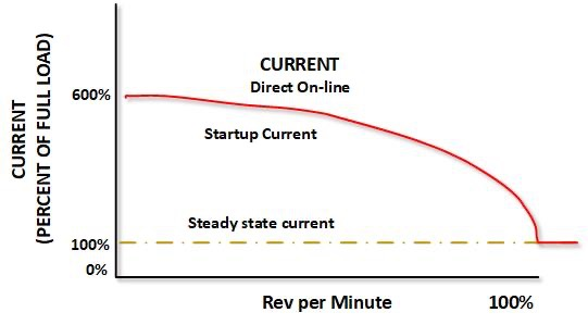
An AC motor soft-starter is a device that controls the application of startup voltage on a motor. The soft-starter is installed between the AC line voltage and the induction motor. With the soft-starter in series with the motor, it can alter the output voltage to the motor to control in-rush current and provide other protections to the motor. Figure 4 shows a typical plot of the startup current and the motor speed in the Direct On-line configuration (no soft-starter). As the figure shows, the initial current is six times the steady state current and once the motor is turning/accelerating, the required motor current tapers off until the motor reaches the final speed.
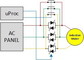
Let’s review the example soft-start circuit shown in Figure 5. The circuit consists of three Diac pairs (pairs are connected in parallel and back-to-back to allow conduction in both directions). Across each Diac pair is 1/3 of a contactor which is used to bypass the solid-state devices with a hard contact closure. This reduces long-term wear on these components as there can be considerable heat dissipated in the Diacs. Under typical operation, when the microprocessor is signaled that the motor is to be started, the soft-starter will open the contact closures and begin controlling the Diacs to adjust the phase start angle.
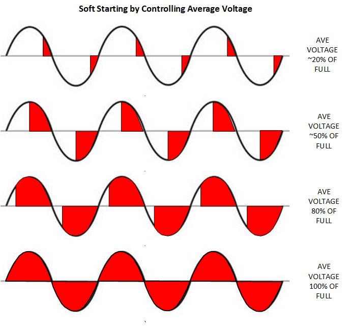
Refer to Figure 6; By varying the conduction phase angle, the motor can have a gradual voltage applied and gradually increased as the motor acceletates. This eliminates the ‘hard-start’ conditions which can excert electrical and mechanical stress on the motor and other nearby electronics. The part of the sine wave covered by red is when the solid-state decive is conducting.
How Does an Asynchronous Motor Soft-Starter Improve Power Quality?
The main PQ advantages for using a soft-starter are that it improves the Power Factor and reduces the likelihood of significant voltage sags. The significance of the benefit depends on the number of motors on any given power source and the size of those motors. Under an inductive load, the current will lag the voltage by 90°. The power factor is calculated by the equation:
Power Factor (PF) = True Power / Apparent Power
-or-
Watts / Volt Amps
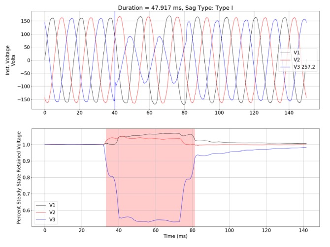
A power factor of 1.0 is perfect, a PF below 0.90 is not desirable. An induction motor inherently has a poor PF as the voltage leads the current by 90°. One way a soft-starter can improve power quality is that instead of having instantaneous startup current surges of more than 500%, The voltage and current (thus power) are ramped up slowly. This will reduce the effects of the surges during the ramp cycle when the current surges are the highest. Voltage sags are defined as a brief (less than one minute) reduction in supplied voltage wherein the RMS voltage falls to <= 90% of the system’s steady state RMS voltage. A voltage sag can be created due to turning on heavy inductive loads such as an inductive motor. The soft-starter slow ramp will reduce these surges which can sub-stantially reduce the demands on the grid. Power Correction circuits can be used in parallel with the motor to perform Power Factor Correction, however, that is a topic for another white paper. Figure 7 shows a Type I voltage sag, where only one phase sags.
Conclusion
As we have discussed the use of motor soft-starters, we have investigated how they can be used to improve the PF of a component. Hard-starts cause wear and tear on equipment, can create voltage sags and surges which can damage other electrical components on the circuit. There is also a cost implication for utility companies for poor PF, as more power must be generated to power a motor, the poor PF will cause more apparent power to be used to achieve the desired True Power. While this can be a complex topic with complex solutions, this white paper hopefully provides a starting point for how PF is calculated, what PF is acceptable, and what can be done to mitigate PF issues in the field.