• Skip to primary navigation
  • Skip to main content

PMI

  • Home
  • Products
  • Library
    • Videos
      • All
      • Bolt Quality Tests
      • Promotional Videos
      • Support Videos
      • Power Quality Decoded
    • White Papers
      • All
      • Artificial Intelligence
      • Case Studies
      • Communications
        • All Communications
        • Cellular Communications
        • General Communications
      • Distributed Generation
      • IEEE Standards
      • Power Quality
        • All Power Quality
        • Analyzing Waveforms
        • Flicker
        • PQ Data Analysis
        • PQ Theory
      • Products
        • All Products
        • Boomerang
        • Boomerang SCADA
        • Box Recorder
        • Canvass
        • Eagle
        • Flex CT
        • Guardian
        • Merlin™
        • Meter Sockets
        • PQ Canvass
        • ProVision
        • Revolution
        • TLAR
        • Using PMI Recorders
      • Voltage
        • All Voltage
        • CVR
        • Voltage Sag
        • Voltage Unbalance
      • Harmonics
  • Training
    • All
    • PDH Eligible Classes
    • On-Site Training
    • Live Webinars
  • Support
  • Our Company
    • About
    • Contact
    • Join Our Team!
    • Receive our Newsletter
    • PQ Resources
    • Power Quality Solutions
  • Account
  • Cart - 0 items

Case Study: Ground Fault Detection

By Mills Landreth · March 1, 2012

← Back to White Papers

Overview

The main breaker tripped in a Motor Control Center. All circuits were meggered and checked out, but no cause was found for the trip. Because none of the load breakers had tripped, an intermittent ground fault or a faulty main breaker was suspected.

A Revolution power analyzer and Flex CTs were installed in tandem to identify the source of the disturbance.

Equipment Setup

A great way to monitor for ground faults is to use the PMI Flex CTs attached to a Revolution and to put the channel four CT around all three power phases (This will work on three phase wye systems where no neutral is pulled to the load that is being monitored).

This setup can be left indefinitely because the Flex CT’s are powered from the Revolution which is in turn powered by the system being monitored. This setup will measure and record any imbalance in current in the three phases. In this case, this is the same current imbalance that the main breaker is monitoring.

A current spike on channel four is much easier to find when viewing the graphs than looking for a spike on one of the phases because in this application channel four will usually show zero amps.

The Revolution was set to record every 15 seconds. This achieves a high enough resolution to compare captured events to time stamps from the distributed control system, however this resolution is low enough to keep the recorded file manageable for long term monitoring.

The Data

After monitoring for several days with no incidents, the main breaker tripped again. The recorded data revealed a series of ground faults. Figure 1 shows an RMS current graph displaying a small ground fault at 06:04 hours.
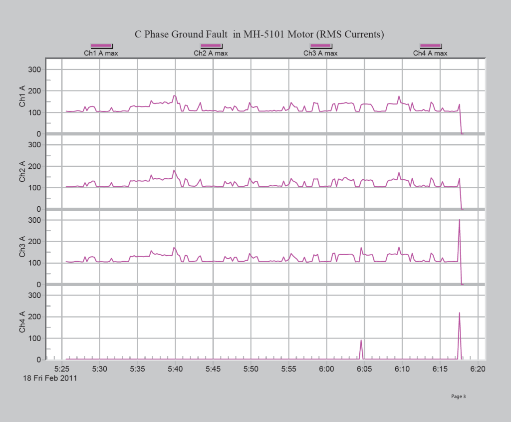
Figure 1. RMS current graph showing small ground fault at 06:04 hours.

This ground fault can be seen again in a waveform capture shown in Figure 2. The MCC main breaker was set to trip at 200 amps of ground current instantaneously, as shown in Figure 3.
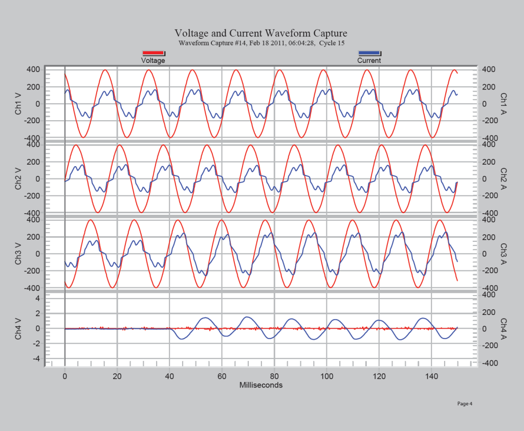
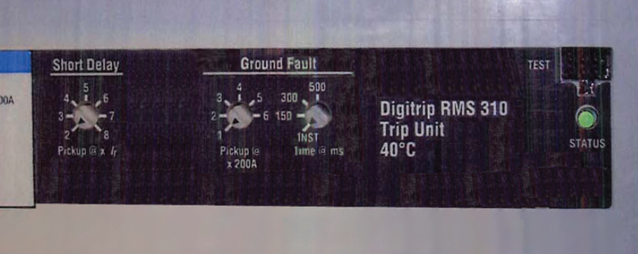
Figure 2. Waveform capture showing the ground fault.
Figure 3. Main breaker trip unit settings

Waveform capture at 06:17:23 hours showed a half cycle ground fault as seen in Figure 4.
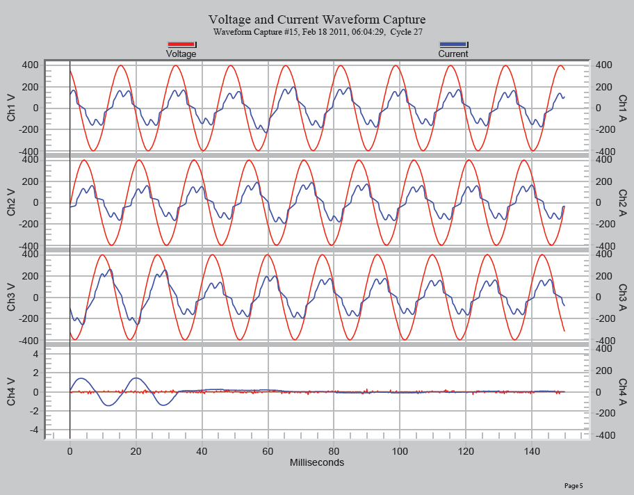
Figure 5. Waveform capture at 06:17:25 hours shows a 3 cycle ground fault

At 06:17:28 hours another 3 cycle ground fault occurred that can be seen in the waveform capture shown in Figure 6. The magnitude and duration of this ground fault was sufficient to trip the MCC main breaker on ground fault. This event is detailed in the Time Current Curves (TCC) and shows why the main MCC breaker tripped and why the load breaker did not trip. This can be seen in Figure 7.
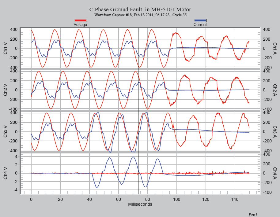
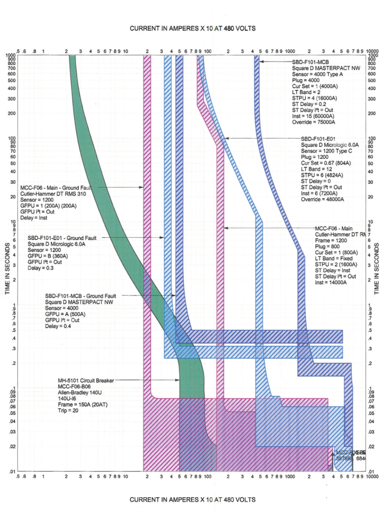
Figure 6. 3 cycle ground fault at 06:17:28 hours.
Figure 7. Time Current Curves (TCC) showing why the main MCC breaker tripped and why the load breaker did not trip.

Note, as shown in Figure 8, the current goes to zero at the breaker trip, but the voltage is slowly decaying. This is caused by intermittent fault clearing and downstream motors acting as generators.
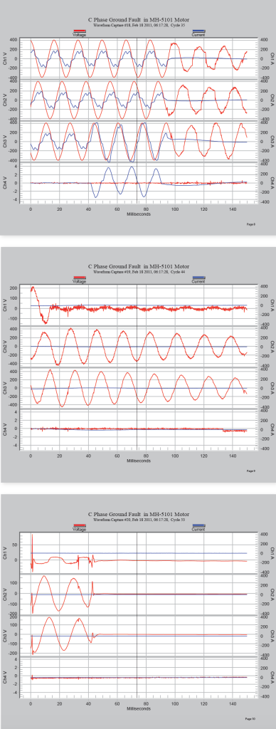
Figure 8. Note the current going to zero at breaker trip, but the voltage is slowly decaying.

The Cause

The material handler was shown to be the cause of the breaker trip. The motor is part of a bag lifting material handling system. It is seldom used and only for short periods of time. The fan in the motor was broken, and as a result, windings were being grounded, as shown in Figure 9.
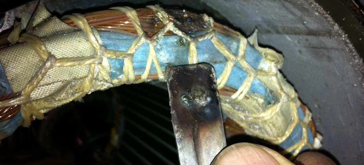
Figure 9. Clockwise from top left: broken cast aluminum fan, piece of fan and set screw, grounded windings

Conclusion

Using the Revolution in tandem with Flex CTs effectively identified the source of a main breaker trip. The Revolution was set at a high enough resolution to compare captured events to time stamps from the distributed control system, however the resolution was low enough to facilitate long-term recording. After several days of monitoring, several ground faults were identified and attributed to a faulty handling system motor.

Have a PQ question? Ask Merlin™ — free.

Send it to askmerlin@powermonitors.com or text (540) 383-3144.

Want the PDF version of this white paper?

Have a PQ question? Ask Merlin™ — free. Send it to askmerlin@powermonitors.com or text (540) 383-3144.

Power Monitors, Inc. — Tools you Need. People you Trust.

Power Monitors, Inc. is an industry-leading product design and manufacturing firm based in Mt. Crawford, Virginia. PMI® strives to solve power quality problems by listening to our customers and working with them to design and manufacture products. Total customer satisfaction is the primary goal of all PMI® staff.

24/7 Tech Support 800.296.4120

Resources

  • White Papers
  • Videos
  • Training
  • Live Webinars
  • PQ Resources
  • Support

Company

  • About Us
  • Contact
  • Careers
  • Newsletter
  • Product Registration
  • Terms & Conditions
800 N Main St, Mt Crawford, VA 22841 | Toll Free 800.296.4120 | Fax 540.432.9430
© 2026 Power Monitors, Inc.