
Abstract
The 3-phase Boomerang sends continuous voltage, current, and power information to Canvass, PMI’s cloud-based data analysis package. The Boomerang and Canvass provide web-based graphing of 3-phase stripchart, daily profile, and histogram data. This whitepaper will explain the process of installing and configuring the 3-phase Boomerang. Wye and delta circuit hookups are shown, along with CT installation. Configuring the Boomerang with cloud-based Canvass and the PC-based NMS software are also reviewed.
Safety Considerations
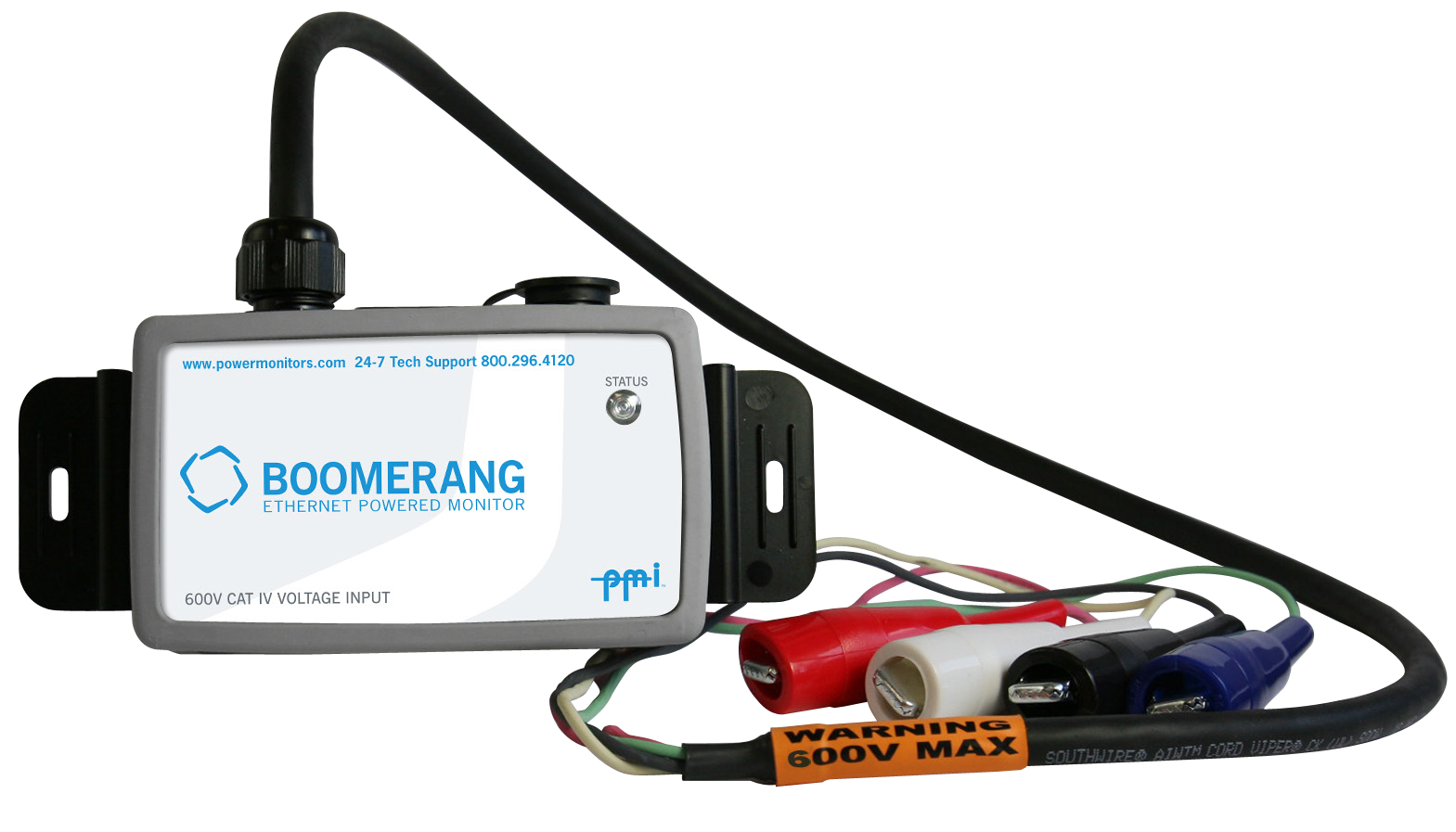
The same care that is required when working with any high-voltage equipment must be taken in order to assure user safety. Please take the time to read the following safety issues before installing the Boomerang (unit shown in Figure 1). If possible, disconnect the power from the lines you plan to monitor until the installation is complete. Inspect the voltage test leads and CT signal cables for damage to the insulation prior to use. Do not use if there are visible cuts or punctures to the cable jacket, or visible inner signal wires.
Connecting the Boomerang
There are two items to connect when installing the Boomerang:
- Voltage clip leads
- Optional CTs (Flex or TLAR – Figure 2)
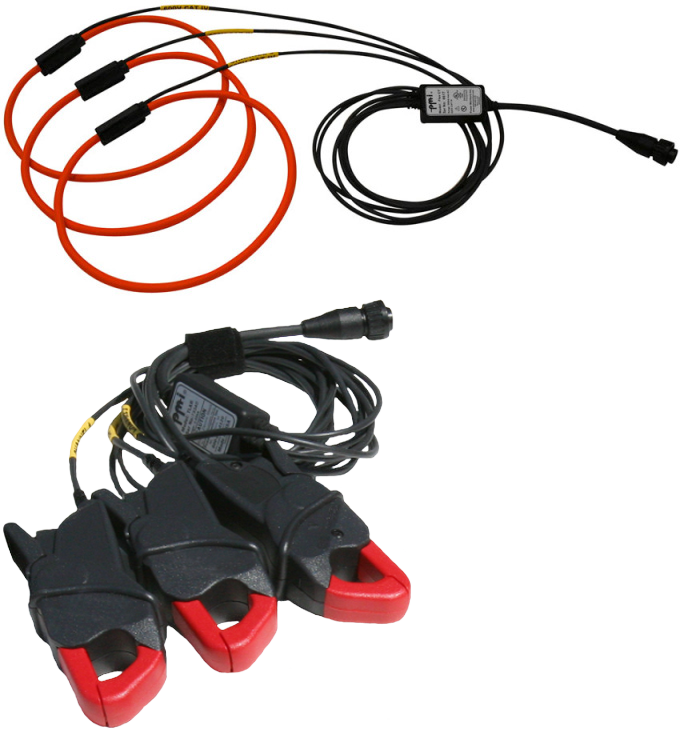
The optional Flex CTs or TLAR current clamps connect to the nine-pin female connector on the side of the Boomerang housing. The Boomerang automatically detects the type of CT connected, but the specific current range should be configured. The Boomerang can be used with TLARs, rated for 20A or 200A, or Ultra Slim Flexible CTs that can be set to ranges of 100A, 1000A, or 5000A. The TLAR clamps are best for 5A secondaries of metering CTs, or other lower current applications. The Flex CTs are best for high current locations. The desired CT range may be set using the Canvass monitoring software or the NMS PC software. If current monitoring is not needed, the Boomerang may be operated with no CTs attached.
To connect the Flex CT or TLAR probes to the Boomerang, insert the 9-pin male connector of the CT output cable into the 9-pin female connector on the side of the recorder and rotate the locking ring. Loop each flexible CT element, or TLAR probe, around the corresponding conductor or bus to be monitored. The raised plastic arrow on the Flex CT connector body, or at the top of the handle of the TLAR current clamp, must point toward the load that is being measured for the correct current-to-voltage phase relationship. Insert the plastic connector plug on one end of the flex CT into the plastic connector socket on the other end, and snap firmly together. Each CT is marked with a channel number; these should correspond to the same channels as the voltage leads.
The Voltage Inputs
The 3-phase Boomerang monitor can read voltage on three input channels. The voltage cable provided with the unit is rated for 300V CAT IV for each channel. These leads are color-coded as follows:
| Channel | Lead | Phase |
|---|---|---|
| Channel 1 | Black | A |
| Channel 2 | Red | B |
| Channel 3 | Blue | C |
| Common | White | Common |
It is useful to connect channel 1 voltage lead last. This connection sequence will assure that all measured voltages and currents are feeding into the Boomerang before any data is sent to Canvass, and will prevent false event triggering that could occur during voltage lead or CT connection. The Boomerang draws its power from the channel 1 input, so connecting this last prevents the Boomerang from powering up and measuring unconnected channels.
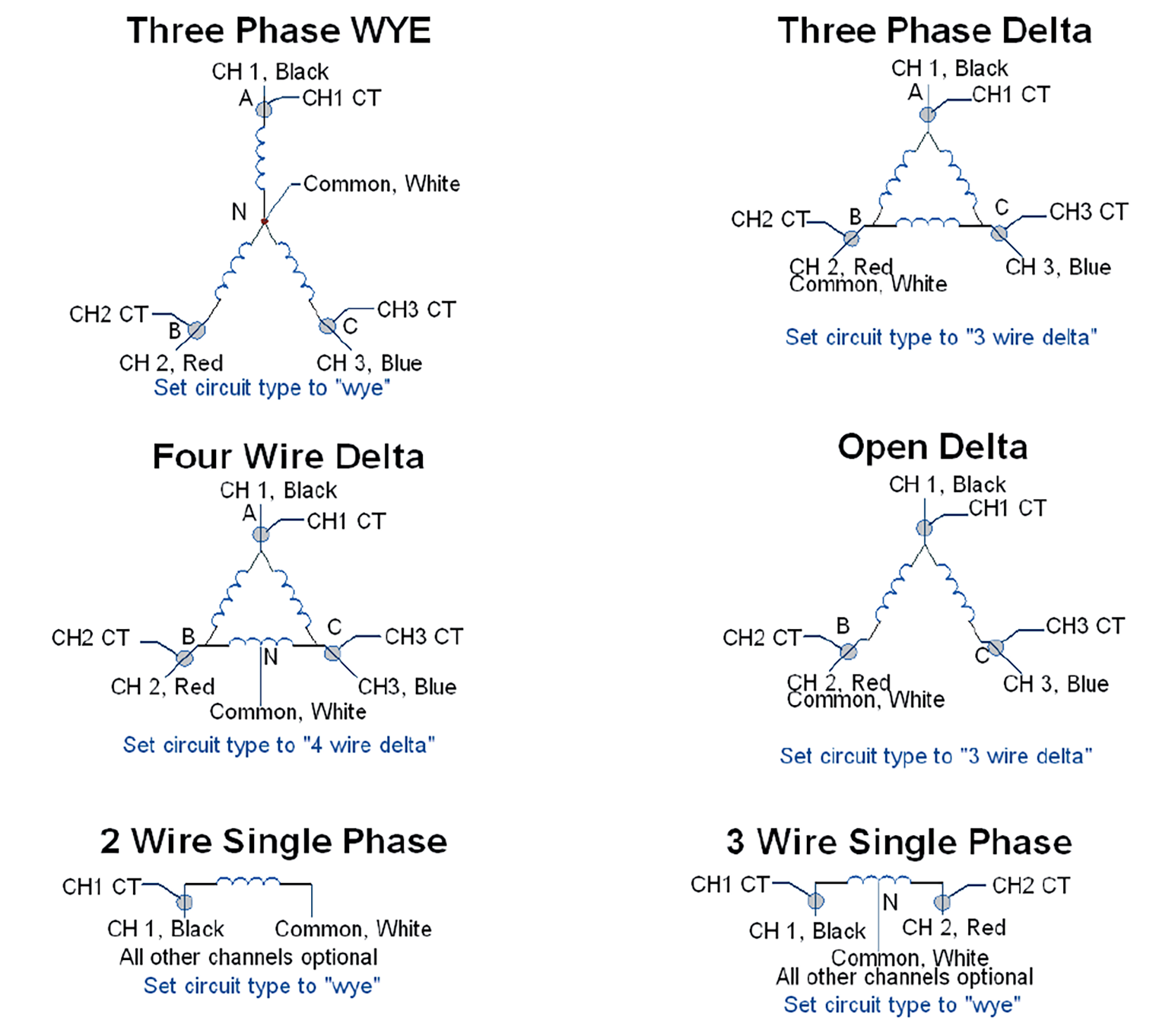
For a wye circuit (shown in Figure 3), channels 1, 2, and 3 connect to phases A, B, and C, and the white common lead connects to the neutral. For a delta, the channel inputs also go to phases A, B, and C, but the white common lead goes on phase B as well. Other circuit types are shown below. The connections are similar to the Revolution and Eagle, with the exception that there is no fourth voltage channel.
Communication
The Status LED on the top of the Boomerang will blink twice red and once green until a cell connection is made. Once it has completed the connection, the monitor will begin transmitting accumulated data to Canvass. The Status LED will blink green once every six seconds so long as the cell connection is maintained. If the unit does not give a regular green flash on the status LED, the unit is not transmitting data to the server. If cell coverage may be an issue, a Boomerang with either an external antenna or antenna kit is available.
Using the Canvass Interface
The Canvass interface is PMI’s cloud-based data analysis portal capable of providing data for single and poly-phase voltage and current monitors in a web browser. With Canvass, the user may view strip charts, histograms and daily profile graphs for every data point that the device has ever registered to the PMI Canvass database.
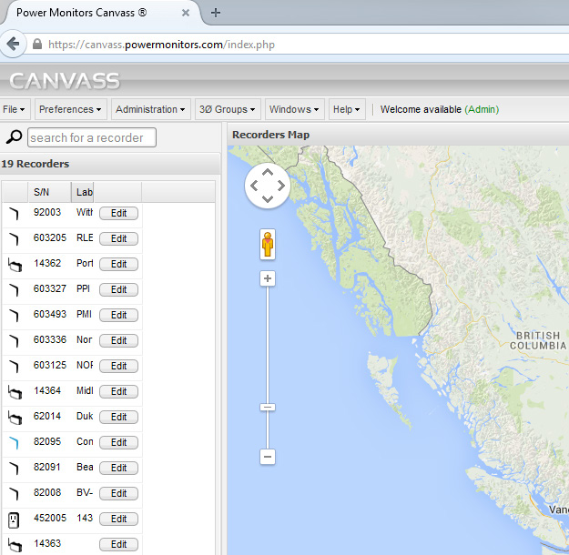
After logging into Canvass, you should be able to view all the Boomerangs you have available listed on the left hand side of the screen, as shown in Figure 4. Devices that are in communication with Canvass will appear in a blue font while recorders that are currently not active will appear in black. To access data from a specific device, double-click on its serial number. This will bring up the window with which you can see the data it has sent to the Canvass database.
The fastest way to verify communications is to select the Stats button. This will show the RSSI, or signal strength of the unit, as well as the last time the unit contacted Canvass. Clicking Burst will send a message to the Boomerang for it to send real-time information for voltage, current, and power for spot readings.
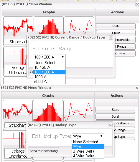
While you are in Canvass, don’t forget to set up the unit. Select the Current Range button to set the FLEX or TLAR max current range or you may use the Hookup Type to specify that you are monitoring a WYE or Delta configured circuit (Figure 5). Select the current range or circuit type, and click “Send to Boomerang” to update the Boomerang configuration. The Canvass server will send a message directly to the Boomerang with the new setting. The Boomerang must be online to receive the setting. Once received, the settings are stored in the Boomerang, and do not need to be sent again unless a change is needed.
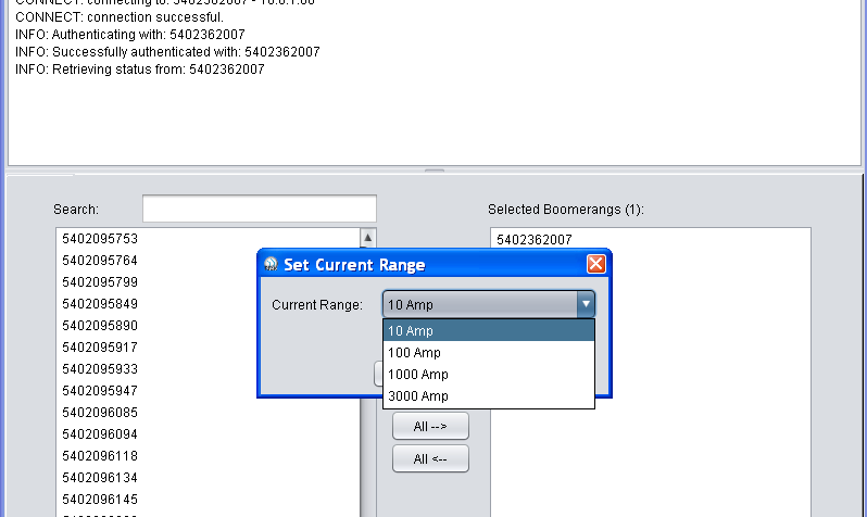
For those customers utilizing the NMS software, you can also use that to set up your configuration. The setup options are under the Network Tab. The “Set Current Range” (Figure 6) will allow you to set your device to the proper current range. The Boomerang unit itself will detect the type of current measuring device you are using, either Flex or TLAR CTs, but the current range should still be set. The “Set Circuit Type” option allows the choice of WYE, and 3 or 4 Wire Delta configurations.
Conclusion
The Boomerang 3-phase monitor provides 1-second detail for voltage, current, power, and voltage unbalance in a small, easy to install wireless package. Instructions for hooking up the Boomerang are shown here, in addition to basic configuration for setting the circuit type and current range in the field or back in the office through a web browser.