
Abstract
This paper explores the unique risks of ferroresonance within solar photovoltaic (PV) installations, specifically focusing on the interaction between step-up transformers and system capacitance. We will examine why solar sites are particularly susceptible during light-loading periods and how high-resolution power quality data from a Seeker or Revolution can be used to distinguish ferroresonance from standard transient events.
Definition
Ferroresonance is a complex, non-linear or chaotic electrical phenomenon characterized by the interaction between a transformer’s iron core (nonlinear inductance) and the capacitance of the distribution system (e.g., underground cabling or capacitor banks). Unlike standard resonance, which occurs at a specific frequency, ferroresonance can cause sustained overvoltages and chaotic waveform distortions that persist until the circuit state is changed.
Common Causes in Solar Applications
In solar environments, ferroresonance typically occurs during inverter wake-up (dawn) or shutdown (dusk), or during a single-phase switching event. Some of the most common triggers include the following:
Wye-Delta Configuration Issues
Many solar step-up transformers utilize a delta-connected primary (utility side) or ungrounded wye, which lacks a path for zero-sequence currents, trapping energy during switching. (For more information on zero-sequence components, see PMI White Paper “Symmetrical Components“.)
Low-Loading / No-Load Conditions
Ferroresonance is most likely to occur when the solar array is “quiet,” such as at night, during heavy cloud cover or during an emergency trip of the inverter bank. In these states, the step-up transformer remains energized by the utility grid, but the inverters are in a high-impedance or idle state, providing zero real power (kW) to the circuit. Without the resistive damping typically provided by active power generation, there is no sink to dissipate the energy oscillating between the system’s capacitance and the transformer’s nonlinear inductance. This allows the resonant oscillations to grow unchecked, driving the transformer core into saturation and resulting in the characteristic high-magnitude voltage spikes.
Cable Capacitance
Unlike traditional overhead distribution lines, utility-scale solar farms rely on miles of shielded, underground medium-voltage (MV) collector cabling to link dispersed inverter pads to the main substation. This insulation and shielding create significant charging current or shunt capacitance. When the transformer is energized but the inverters are not producing power, this cable capacitance forms a resonant tank circuit with the transformer’s nonlinear magnetizing reactance. In this state, the underground network acts as a reservoir of reactive energy that can oscillate back and forth with the transformer core. If a switching transient or a momentary voltage dip pushes the transformer into saturation, the energy stored in these long cable runs can sustain and amplify the ferroresonant state, leading to catastrophic insulation failure.
Single-Phase Operations
Ferroresonance is frequently initiated by unbalanced switching or the operation of single-phase overcurrent protection, such as a blown fuse or a single-phase recloser on the utility side. When one or two phases are opened while the third remains connected, the energized phase provides a path for current to flow through the transformer’s primary windings. This current then seeks a path to ground through the capacitance of the de-energized cables on the open phases. This creates an effective resonance network where the transformer’s non-linear magnetizing reactance is forced into an unbalanced state of excitation. This specific electrical geometry is the primary mover for ferroresonant states, often resulting in phase-to-ground voltages on the open phases that are significantly higher than the nominal system voltage.
How to Identify with PMI PQ Recorders
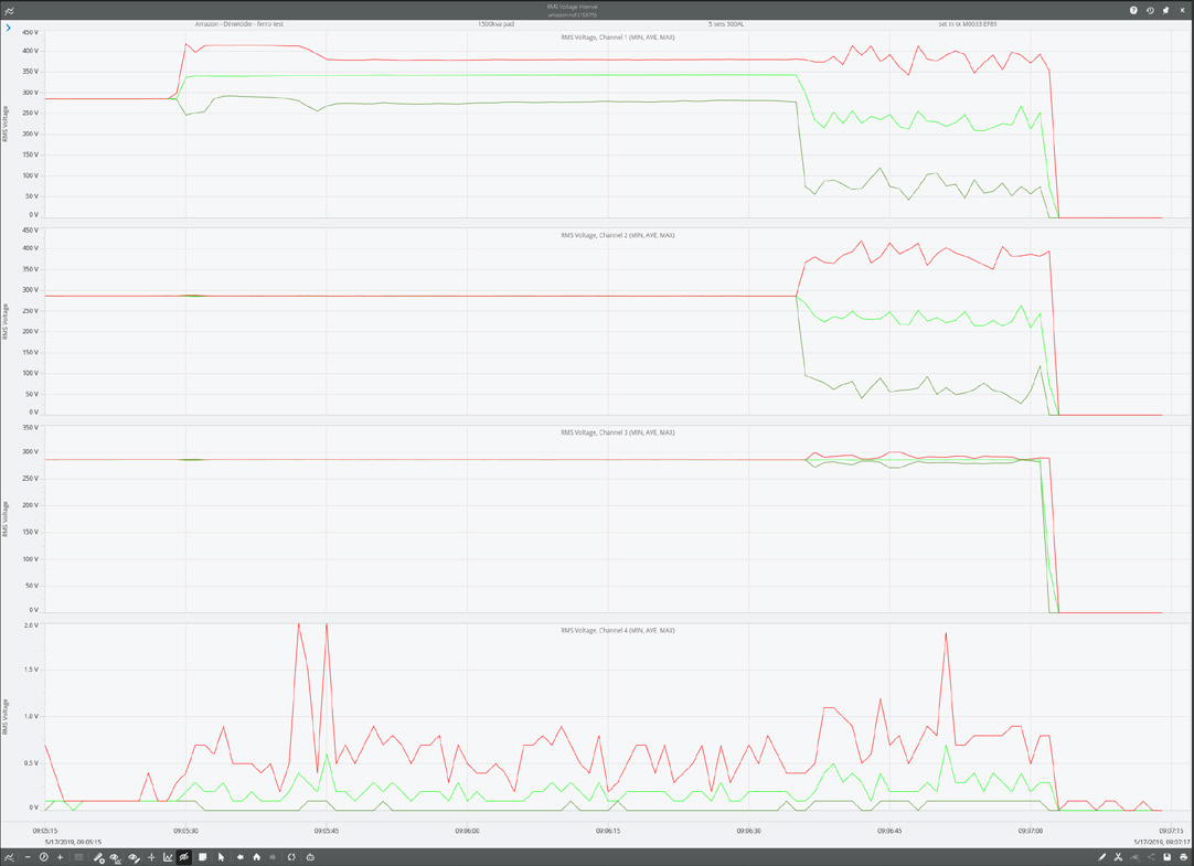
Identifying ferroresonance requires looking past simple high voltage alerts and analyzing the physical signature of the magnetic saturation. A great first place to start is with RMS Voltage stripcharts. Using PQ Canvass the signature to look for is sudden, sustained jumps in RMS voltage that do not correlate with utility-side regulation. Ferroresonance frequently displays “mode-hopping”, where the voltage jumps between distinct levels in a chaotic fashion.
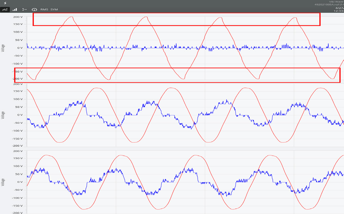
The next place to look is in the triggered waveform captures. The features to look for here include high-magnitude, low-frequency distortion. Typically, the peaks of the sine wave will look “peaked” or “jagged” rather than rounded like one would find in a clean sine wave. These peak distortions are a strong indicator that the transformer core is being driven deep into saturation every half cycle.
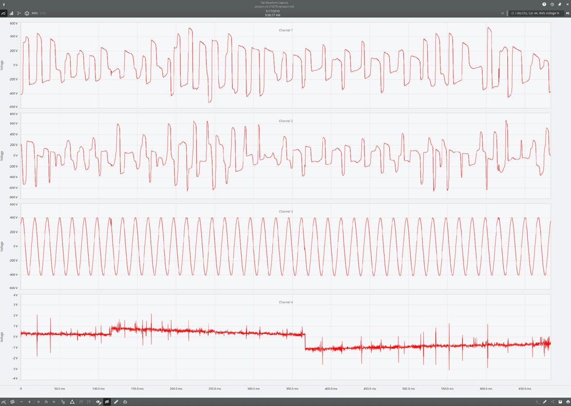
In some instances, where the harmonic distortion is so great that the recorder itself has difficulties phase locking to the 60Hz fundamental, the wave shape looks almost completely nonsensical — it’s barely distinguishable as a sinusoidal signal.
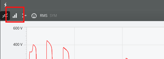
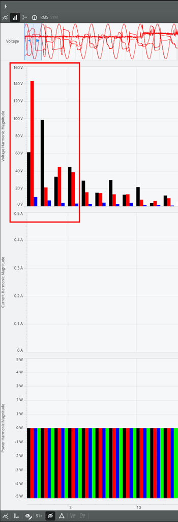
Finally, while in the waveform analysis tool within PQ Canvass, the user can click on the Harmonics button.
Ferroresonance frequently presents with high magnitude odd harmonics (3rd, 5th and 7th). Note: if the user recorded interharmonics with a Revolution, then a quick check in ProVision to look at the sub-harmonics in the 20Hz to 30Hz range can surface the “smoking gun” of ferroresonance behavior. This sub-harmonic range is a common feature of the phenomenon.
How to Resolve the Issues
Mitigating ferroresonance involves shifting the system’s impedance or providing a path for the energy to dissipate.
Secondary Loading (Resistive Damping)
One of the most effective ways to suppress ferroresonant oscillations is the installation of a resistive “dummy load” or a dedicated damping resistor bank on the transformer secondary. In a ferroresonant circuit, energy oscillates between the inductive core and the cable capacitance with very little loss. By adding a permanent resistive load, you introduce “damping” into the system. This resistor acts as an energy sink, consuming the reactive power that would otherwise sustain the resonant state. For solar applications where efficiency is a concern, these resistors can be sized to represent only a small fraction of the transformer’s rating (often less than 2%), or they can be managed via a controller that only engages the load when the inverters are idle and the system is at its most vulnerable.
Neutral Grounding and Zig-Zag Transformers
Many solar installations use delta-connected primary windings, which lack a solid ground reference and allow the neutral to shift or float during a disturbance. To resolve this, a grounding bank, most commonly a Zig-Zag transformer—can be installed on the utility side of the solar step-up transformer. The Zig-Zag connection provides a high-impedance path for normal balanced traffic but a very low-impedance path for zero-sequence (ground) currents. By effectively tying the system neutral to ground, the Zig-Zag transformer prevents the phase-to-ground voltage on the healthy phases from skyrocketing during a single-phase opening, thereby short-circuiting the conditions required for a ferroresonant tank circuit to form.
Three-Phase Switching and Protective Relaying
Because the prime mover of ferroresonance is often the loss of a single phase, the most robust preventative measure is the implementation of three-phase gang-operated switching. By ensuring that all three phases of the transformer are energized or de-energized at the exact same moment, the risk of unbalanced excitation that leads to resonance is greatly reduced. Furthermore, modern protective relays can be programmed with negative sequence voltage or phase loss logic. When a single-phase event is detected upstream, the relay can be set to trip the main three-phase breaker immediately, clearing the transformer from the grid before a sustained ferroresonant oscillation can cause thermal damage to the core or insulation.
Specific Switching Sequences
In many cases, ferroresonance can be avoided by strictly adhering to a switching sequence that ensures the transformer is never energized in an unloaded state while connected to long runs of underground cabling. By modifying the energization procedure—for example, ensuring that the collector system cabling is energized from the substation first, followed by the systematic closing of the low-voltage (LV) breakers at the inverter pads—you can manage the capacitive charging current more effectively. Furthermore, if the system allows, preloading the transformer by ensuring the inverter control power is active and ready to synchronize immediately can provide the necessary damping at the moment of energization.
Conclusion
Ferroresonance remains a significant threat to the longevity of solar step-up transformers and system insulation, particularly during periods of low inverter activity. By utilizing high-resolution waveform capture and RMS trending, operators can accurately diagnose these nonlinear events and implement effective damping or grounding strategies to protect their infrastructure.