
Abstract
Substation circuit loads are mostly inductive, dominated by distribution transformers and large motors. Canceling a portion of this inductance with Power Factor Correction capacitors (PFCs) improves power factor by reducing resistive losses. However, introducing capacitance also creates resonances, or frequencies where the system impedance peaks. Estimating the primary system resonance is important for understanding the implications of adding or changing PFCs on a feeder. A simplified formula for this estimation is shown in this white paper.
Some Basic Formulas and Definitions
Reactance is the AC extension of resistance in a DC circuit. More fundamentally, reactance is the opposition to the flow of AC power flow due to the absorption in an electrical field (capacitance) or a magnetic field (inductance). Mathematically, by extending the concept of resistance to complex numbers, total circuit impedance includes a real part (resistance), and an imaginary part (reactance). Capacitive reactance is negative imaginary; inductive reactance is positive imaginary. When capacitors and inductors are both present, their opposite signs allow them to cancel if their magnitudes are equal, leaving just resistance in the circuit. The frequency where this occurs is the resonant frequency.
The standard notation for reactance (and the notation that will be used in this paper) is XL for inductive reactance and XC for capacitive reactance.
Resonance, as mentioned above, is defined as the frequency at which XL = XC, with both being defined below:
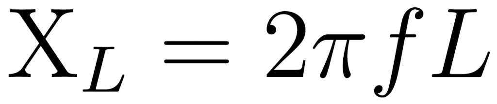
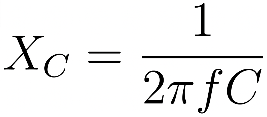
where XL is inductive reactance, L is inductance (in Henries), XC is capacitive reactance, C is capacitance (in Farads), and f is frequency (in Hertz).
Equating these two expressions gives:
and then solving for :
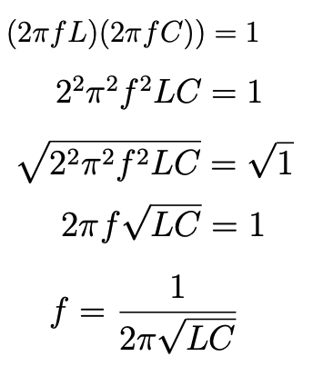
Mathematically speaking, the portion is called angular velocity and is typically denoted as ω. This will help simplify things in the next section.
Harmonics
Harmonic frequencies are whole multiples of a fundamental (or base) frequency. In a 60 Hz electrical circuit, the first harmonic, known as the fundamental, is simply 60 Hz. The second harmonic is 2×60 = 120 Hz, etc. Given the equation above for angular frequency , we can say that the expression for a harmonic is
Computing System Resonances
Given the definitions of angular velocity and harmonics above, we can do some substitutions to make things a little simpler.
First, let us restate the expressions for inductive and capacitive reactance (XL and XC) using our newer notation and introducing n for a harmonic multiple, and set them equal to one another:
Solving for n gives:
(1)
Note here that we are solving for the harmonic multiplier, not raw frequency in Hertz. This formula may be used directly if the feeder reactance and PFC capacitance are known. In most cases, feeder capacitance is mostly due to installed PFCs, so their KVAR or MVAR size may be translated to Farads. The capacitor MVAR rating is the amount of reactive power drawn by the capacitor at a specific line voltage V, which is:
and solving for XC or C gives:

Unfortunately the feeder inductance is not so easily computed. However, it’s possible to recast the resonance equation in a form using the system short circuit MVA rating, which can serve as an approximation to the inductance. This formula also uses the capacitor MVAR value directly, avoiding the need to convert to raw Farads.
In order to proceed we are going to have to make an assumption. The feeder impedance is mostly reactive with little resistive component — in other words, a high X/R ratio. Remember that impedance Z is a complex sum:

This allows us to use the following:
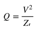
This allows us to use the relationship where Q is reactive power, and ZL = XL for a purely inductive circuit.
Now consider MVASC, the short circuit MVA rating of a feeder. This is maximum current, or equivalent MVA at a specific line voltage, that would flow with a shorted load when fed from a source of infinite capacity. With an inductive impedance, apparent power (VA) is equal to reactive power (Q), so we can approximate:
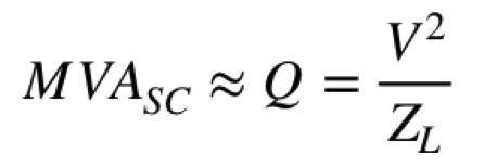
Solving for XL or L gives:

We now have expressions for C and L, and also XC and XL from readily available information (installed PFC size and known feeder short circuit values). Substituting XC and XL from (2) and (3) into (1) gives:
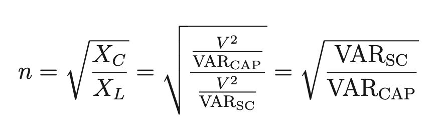
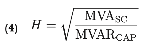
Switching to MVARs and using the more familiar H for harmonic number gives the final approximation:
Example
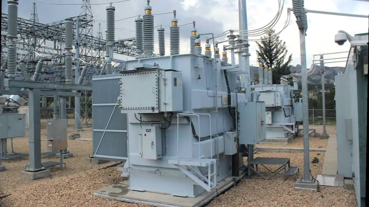
As an example, consider the substation transformer in Figure 1. This is an 18 MVA LTC transformer with a 12,470Y/7200V secondary. This transformer has a known MVASC of 140 MVA at nominal line voltage and tap position. The substation has 1.4 MVAR capacitance installed per phase, or 4.2 total. Using equation (4) gives:
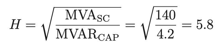
This gives a resonant frequency of 5.8 × 60 Hz = 350 Hz. This transformer’s actual circuit inductance is also known to be around 3 mH (per phase). Converting 1.4 MVARCAP to Farads gives 72 μF. Using those values and calculating for frequency directly gives:

agreeing closely with the estimate of 350 Hz.
Conclusion
The feeder resonance approximation formula (4) is easily calculated from readily available system information. The derivation of this formula is presented here. A resonance frequency check should be performed any time there’s a change in PFC values, or if oscillatory transients are creating problems for customers or switching equipment.