
Abstract
Troubleshooting electrical power and equipment failure incidents is not unlike a crime scene investigation that establishes not only collateral damage, but also attempts to determine, using investigative techniques and on-scene evidence, the timeframe, the culprit, and any other incriminating evidence.
Whenever electrical equipment fails unexpectedly and without warning, it requires investigation of all the facts surrounding the failure, and can result in a catastrophic event, costly downtime, loss of revenue, or replacement of equipment. Such was the case during a recent loss of two main industrial chillers. With a common failure of two 3 phase chiller fuses on two phases, engineers at Gainesville Regional Utilities suspected the cause was an electrical power source problem feeding the chillers. This case study examines the incident and the resulting investigation of its cause.
Initial Conditions
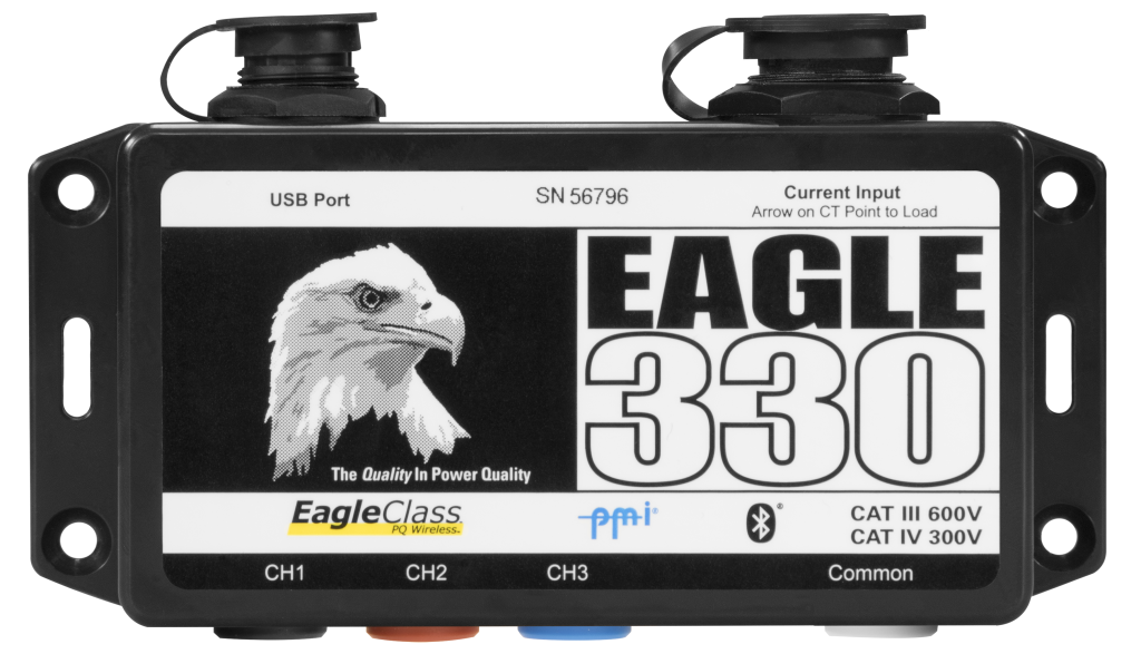
The utility providing power to this customer site had previously installed one of their PMI Eagle 330 portable 3 phase power recorders (Figure 1) at the main service entrance to record power during some weather predicted storms, to enable any incident data to be captured. This decision proved to be a vital part of evidence during the investigation.
Review Of Evidence
According to evidence provided by the customer, at approximately 5:30pm on Friday, March 16th 2012, the central two main chillers blew both Phase B and Phase C fuses on the respective Motor Control Center (MCC) panels, and supply personnel had to resort to running the emergency chiller, as each chiller had specialized fuses installed.
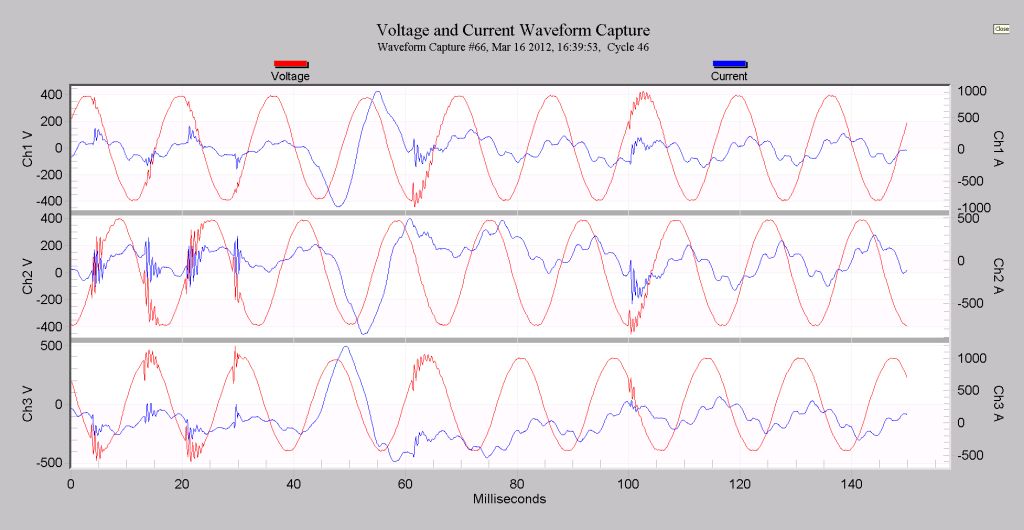
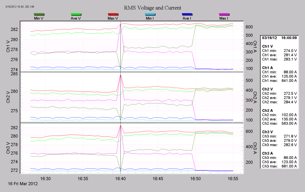
Initially, after investigating the system’s event log, no specific event could be attributed to a loss of one chiller, let alone two. However, after downloading data from the Eagle 330 PMI PQ Recorder that had been installed on an adjacent transformer fed from the same medium voltage distribution feeder, a significant power interruption and condition was noted, at the same time– 5:39pm, on the same Friday afternoon in March of 2012. It became clear these waveform events were significant and required investigation by the utility’s PQ Group.
Once the recorder data had been reviewed by the utility PQ Engineers some conclusions were drawn and an explanation of the sequence of events started to emerge as shown in Figures 2 and 3. From the three phase voltage and current waveforms show on the right, it was clear that the two phases on Feeder B and Feeder C suffered transitory voltage surges which were the result of switching at a 12.47kV capacitor bank located within two blocks north of the customer on the main distribution feeder. The operation of this capacitor bank was verified from within the utility application software.
Conclusion
Over the last three years this utility had witnessed four or five similar events and all of these events were related to a faulty capacitor bank switching, but because the evidence obtained from the field was inconsistent in all of the previous events, the utility could not positively identify the root cause of these transients; it could however verify they all exhibited similar conditions. The suspected transients captured by the Eagle 330 PQ recorder may have been caused by a bad batch of vacuum switches, bad connections, or bad cutouts. After further investigation of a failed capacitor bank by qualified personnel, it was determined that A & B phase arrestors had blown, and B phase insulator on the main line had been burnt and had to be replaced. It was clear and safe to assume the capacitor bank was hit by some voltage surge, possibly lightning. And with a high degree of probability the transient overvoltage caused by the switching capacitor bank resulted in the MCC B&C fuses to blow.
None of this analysis and investigation would have been possible without the use of the Eagle 330 portable power monitor.