
Engineered Asymmetry
Audiophiles routinely spend thousands of dollars on vintage vacuum tube amplifiers to deliberately inject their music with what power engineers spend millions trying to eliminate: harmonic distortion. Vacuum tubes naturally produce octave-related multiples of the original note that sound rich and full-bodied to the human ear. This pleasing sound is actually the result of even-order harmonic distortion (the 2nd, 4th, and 6th).
Most modern audio amplifiers use symmetrical output stages that cancel even-order products — which is why audiophiles go out of their way to buy single-ended tube designs that don’t. For them, asymmetric gain is a coveted feature that produces those prized even harmonics. This even-vs.-odd distinction reveals a fascinating parallel between audio fidelity and electrical power quality.
The very same harmonic orders are a problem on a power system. Where a tube amp’s asymmetry is engineered in, asymmetry on a power line means something has physically changed, like a DC bias on a transformer, a failing rectifier, or a malfunctioning load. By analyzing harmonic content, engineers can determine what a system is doing — and more importantly, when something has gone wrong.
A Quick Foundation
For readers unfamiliar with harmonics in power systems, PMI’s white paper Harmonic Calculations provides a thorough treatment of the underlying Fourier mathematics. In brief: the fundamental frequency on a North American power system is 60 Hz. Harmonics are integer multiples — the 2nd harmonic is 120 Hz, the 3rd is 180 Hz, the 5th is 300 Hz, and so on. These components are generated when nonlinear loads draw current in non-sinusoidal patterns, distorting what would otherwise be a clean voltage sine wave. A linear load draws current in proportion to the voltage applied; a resistor is the simplest example. A nonlinear load does not — a rectifier, for instance, conducts only when the voltage exceeds a threshold, pulling current in sharp pulses rather than a smooth sine wave.
That distorted current flowing through system impedance produces a distorted voltage drop — and every other load sharing the same supply sees that distorted voltage. Each additional nonlinear load on the circuit contributes its own distortion back into the line, so the cumulative effect at the feeder level can be substantially worse than any single source would produce alone. Resonances formed by system inductance and power factor correction capacitors can further magnify harmonic currents and voltages.
One useful measure when quantifying the severity of distortion is Total Harmonic Distortion (THD), which expresses the total harmonic content as a percentage of the fundamental. For current-based assessments, IEEE 519 uses a related metric called Total Demand Distortion (TDD). Instead of normalizing against the fundamental, TDD normalizes against the maximum demand load current at the point of common coupling (PCC). This distinction matters because current THD can spike misleadingly during light load conditions, while TDD stays anchored to the system’s actual capacity.”
Why Odds Frequently Appear
Measure the harmonic spectrum of nearly any load on a modern power system, and the pattern is the same: 3rd, 5th, 7th, 11th — odd orders only, with no significant energy at the 2nd, 4th, or 6th.
That consistency comes from a single physical fact. A full-wave rectifier conducts on both halves of the AC cycle. A variable frequency drive’s front-end converter draws current the same way whether voltage is swinging positive or negative. A switch-mode power supply charges its DC bus capacitor on both half-cycles equally. The positive and negative halves are mirror images of each other. When that mirror holds, all even-order harmonic components cancel to zero. Only the odds survive.
Three-phase rectifier loads narrow the pattern further. The harmonics produced by a p-pulse rectifier follow h = kp ± 1, where p is the pulse number and k is any positive integer. A standard 6-pulse VFD — the workhorse of industrial motor control — produces a spectrum including the 5th, 7th, 11th, 13th, 17th, and 19th. All odd. No evens. Current distortion from a 6-pulse drive typically ranges from 30% to over 100% current THD, depending on impedance and whether line reactors are present. Single-phase loads like computers, CF/LED Lamps, and compact fluorescent lamps push even higher, routinely reaching 100% to 140% THD with the 3rd and 5th dominant. Their low absolute current levels limit their individual effects on voltage.
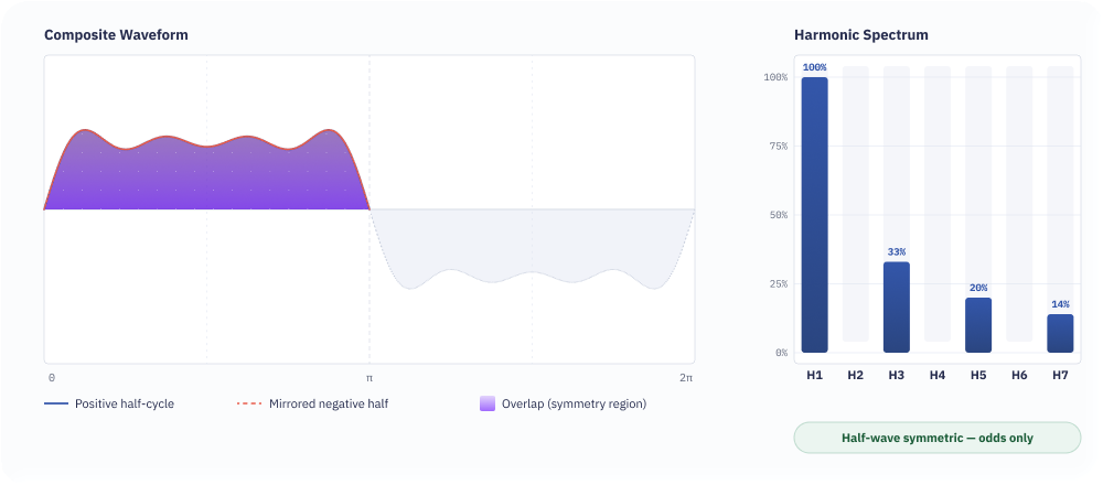
Those numbers hold across every major class of harmonic-producing equipment. Power system harmonic sources generally fall into three categories: ferromagnetic devices (transformers, motors), arcing devices (arc furnaces, arc lighting), and electronic devices (rectifiers, inverters). A transformer driven into saturation produces a magnetizing current that is entirely odd-order — 3rd at roughly 50% of fundamental, 5th at 20%, 7th at 5%, 9th at 2.6%. A single-phase arc shows the same odd-only fingerprint: 3rd at 15%, 5th at 4%, 7th at 1.5%, 9th at 1.0%.
The pattern tends to hold at the distribution level as well. Residential feeders, loaded primarily with single-phase rectifier-based equipment, generally show the 3rd and 5th harmonics as the dominant components. When the phase angles of those low-order harmonics happen to align across households, the currents add rather than cancel — which can push aggregate distortion on a feeder higher than what comparable commercial or industrial circuits typically carry.
Why Evens Demand Attention
Odd harmonics are the baseline. Engineers expect them, plan for them, filter them. Even harmonics — the 2nd, 4th, 6th — carry a different message. Their presence means the positive and negative half-cycles of the waveform are no longer mirror images of each other.
That lost symmetry always traces to something abnormal. A half-wave rectifier conducts on one half of the AC cycle and blocks the other. A transformer subjected to DC bias shifts its operating point on the core’s saturation curve, so one half-cycle drives it deeper into saturation than the other.
A component failure that changes how current flows on one polarity but not the other produces the same result.
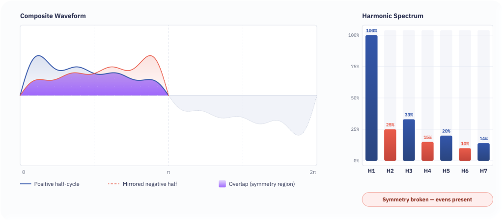
Even harmonics do not necessarily mean DC is present in the signal itself. They mean the waveform has lost its half-cycle symmetry with a resulting DC shift. On a power system, that loss never happens by design.
How IEEE 519 Walks The Line
IEEE Std. 519-2014 sets harmonic distortion limits for power systems. Table 2 covers current distortion for systems rated 120 V through 69 kV, organized by odd harmonic order from the 3rd through the 50th.
For a system with a short-circuit ratio (I_SC/I_L) less than 20, the individual odd harmonic current limit for orders 3 through 10 is 4.0% of maximum demand load current. Total Demand Distortion is capped at 5.0%. For a system with I_SC/I_L greater than 1000, those limits rise to 15.0% for low-order odds and 20.0% TDD.
Even harmonics appear in the table’s footnotes. Footnote (a) limits even harmonics to 25% of the odd harmonic limits — so on a system where the odd limit is 4.0%, the even limit is 1.0%. Footnote (b) states that current distortions resulting in a DC offset, such as those from half-wave converters, are not allowed.
Compliance is assessed statistically. The weekly 95th percentile of short-time (10-minute) measurements must fall within the Table 2 values. The weekly 99th percentile must remain below 1.5 times those limits. The daily 99th percentile of very short-time (3-second) measurements must stay below 2.0 times the limits. Even harmonics, already at one-quarter of the odd thresholds, are held to the same statistical requirements.
Consequences of Distortion
Odd harmonics are the everyday reality of a modern power system loaded with nonlinear equipment, and they produce a well-understood set of problems. Harmonic currents cause additional heating in conductors, neutral wires, and bus bars — and at higher frequencies, skin effect increases conductor resistance, amplifying those losses. Transformers take the hit as increased core losses from eddy currents and hysteresis, often requiring de-rating to operate safely.
Triplen harmonics — the 3rd, 9th, 15th, and their odd multiples — behave unlike any other harmonic order in a three-phase system. On all three phases, triplens are zero-sequence: they peak at the same instant, in the same direction. In a wye-connected, four-wire system, that means they sum in the neutral conductor rather than canceling as balanced fundamental currents do. A neutral sized for 60 Hz current can carry three times the per-phase triplen load — and overheat doing it. Devices downstream may malfunction as the triplen voltage drop in the neutral misshapes the line-to-neutral waveform.
Delta-connected windings handle triplens differently. With no neutral path, zero-sequence currents circulate inside the closed delta loop and never reach the line conductors. This is why delta-wye transformers are often used to trap triplens — the delta winding absorbs the circulating current as heat in its windings, stopping propagation upstream. The tradeoff: additional winding losses that must be accounted for in the transformer’s thermal design.
Power factor correction capacitors are particularly vulnerable. Capacitors present a low-impedance path at higher frequencies, which attracts harmonic currents. When capacitor reactance and system inductance create a resonance near a harmonic frequency, the result can be blown fuses, failed capacitor cans, or tripped breakers. Powerline communication systems and sensitive electronics are also susceptible to interference.
Even harmonics produce all of these same effects — but they add another. Because the conditions producing even harmonics often involve a DC component in the waveform, they push transformer cores into asymmetric saturation. Equipment built for symmetrical AC operation is not designed to handle that condition. The resulting overheating, increased magnetizing current, and mechanical stress accelerate failure. IEEE 519, Footnote (b), addresses this directly: current distortions that produce a DC offset are not allowed.
The Cost of Asymmetry
That prohibition exists because asymmetric saturation destroys equipment that was never built to handle it. When we think back to the tube amplifier, its designer wanted those even harmonics and shaped the circuit around them. The transformer on a 13 kV feeder was not.
Odd harmonics show up wherever nonlinear loads operate normally. They cost money in conductor heating, capacitor stress, and transformer de-rating — but they are budgeted for. Filters attenuate them. K-rated transformers absorb them. IEEE 519 allocates room for them across five tiers of system strength. Even harmonics get one-quarter of that room. Below a short-circuit ratio of 20, the ceiling drops to 1.0% of demand current. Half-wave rectification — the most direct path to a DC offset — is not allowed at all.
Further Reading
For deeper exploration of the topics covered in this white paper, PMI offers several companion resources:
- WP353 — Harmonic Calculations: A thorough treatment of Fourier mathematics as applied to power system harmonic analysis, including the Discrete Fourier Transform, harmonic magnitude and phase angle calculations, and interharmonics
- WP159 — Finding the Source of Harmonic Problems Using Harmonics & Phase Angle: Explores methods for determining whether harmonic distortion originates from the utility source or the customer load, using harmonic power direction and phase angle analysis.
- WP131 — Understanding the Harmonic Analysis Report: A guide to interpreting harmonic analysis data from PMI instruments.
- WP376 — 60Hz Phasors and Extended PQ Measurements: Covers phasor analysis and extended power quality measurements beyond basic harmonic assessment.