
Abstract
The Boomerang family of cell-connected distribution monitors continues to expand. This expansion includes updated hardware, added features and new capabilities. These changes along with customer input have driven the need for additional DNP3 (Distributed Network Protocol 3) points to be added to the PMI point map. Whitepaper 118 (An Overview of DNP3 and the Boomerang Point Map) contains PMI’s original point map created to support the single phase, voltage-only Boomerang 2S. This first version of the point map was superseded by the version 2.0 map to support the growing Boomerang product line as described in WP167 (Boomerang DNP3 Point Map 2.0). This whitepaper details the additions to the 2.0 map since the release of WP167 nearly four years ago.
DNP3 Points Defined
The DNP3 protocol is used by SCADA systems to monitor and control a wide range of external devices. The protocol itself is freely available to device manufacturers so that products from different vendors can be utilized on the same SCADA system. The DNP3 protocol is very generic in its method used to access the data on a device (known as RTU’s, remote terminal units or outstations).
The protocol utilizes a series of groups and points within each group. The groups of data types (binary input, analog output, etc.) are defined by the protocol while the points within each group are defined by the manufacturer of the outstation. Some of the new points that have been added to the Boomerang map expand groups that are already in use. Other points have been created within previously unused groups representing new types of input and output being supported by some Boomerangs.
New Points for All Boomerangs
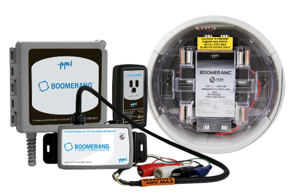
Some of the newly added points are available on all versions of the Boomerang utilizing the 2.0 point map (excludes the voltage-only Boomerang 2S). A Boomerang firmware update may be required to gain this functionality.
Binary counters (group 20) now has a point (point 23) for monitoring the total time in seconds that the Boomerang has been successfully connected to the cellular data network. This may be useful in conjunction with the run time (point 20) for monitoring the network availability.
There have been two general information points added to the analog input group (group 30). These are the Boomerang’s firmware version on point 20 and the device serial number on point 21. These points can be read at any time and may be useful for ensuring all Boomerang outstations are operating at the same firmware level or to check availability of all expected devices.
Analog input deadband support (group 34) has been added and is useful as an alternate (or additional) means of monitoring variations in voltage, current and power. A common method for monitoring values is for the SCADA master to retrieve data periodically and act on the results. Deadbands allow for setting a deviation zone for a given measurement. If the current value (voltage, current or power) varies from the last value that caused an event by more than the deadband amount in either the positive or negative direction then a new analog input event is generated. Up to 50 events will be stored with an associated time of occurrence and can be retrieved by the SCADA master on a periodic basis.
The Boomerang can also be configured to send events asynchronously as they occur which can help to reduce the amount of data being consumed on the Boomerang’s cellular data plan. The deadband points can be written at any time or can be read to see the active deadband values. A deadband value of zero for a given measurement disables the associated deadband processing. Zero is the default setting for all deadbands.
Analog outputs (group 40) has a new writable configuration point (point 25) to allow a SCADA master to set the duration of the averaging window used by the Boomerang when reporting averaged voltage, current and power values. Group 40 also has new channel oriented points for saving the initial deadband settings used at power up instead of having the SCADA master set them at run time.
The Eclipse – DER Remote Control Solution
PMI’s soon to be released Eclipse DER control device can control remote equipment as well as optionally monitor remote voltage and current levels. Designed specifically for the needs of DER remote monitoring and control, the Eclipse adds two binary inputs and outputs with their own DNP3 points. The binary inputs return a true result when 120 VAC is present on the input terminal, and false when this voltage falls below approximately 60 VAC. There are also two binary outputs connected to relays within the Eclipse that can be wired to external devices or other controllers.
These Form C relays provide both normally open and closed contacts for maximum flexibility. The inputs and outputs are managed by a utility SCADA master to monitor and control devices external to the Eclipse.
The two binary inputs (group 1) have been created as points 20 and 21. These points can be read at any time to query the status of the input for the presence of 120 VAC. Two binary outputs (group 10 or group 12) are used to control the relay outputs on points 20 and 21. The binary outputs reside in two different groups due to the flexibility built into the DNP3 protocol. The group 10 points use simple write commands to the outputs without a status return indicating the actual state of the output.
The status returned from a group 10 write reflects the success or failure of the command and not the actual effect on the output. The usage of group 12 requires the output to be first selected and then operated upon. This method will return the actual state of the output or an error code upon command failure.
Conclusion
The Boomerang family of products continues to expand and gain additional functionality. Sometimes new capabilities are added based on industry needs and occasionally based on customer request. The DNP3 protocol has the flexibility to handle these changes with the addition of select data points added to the proper groups for complete coverage of the Boomerang feature set.
Group 1 – Binary Input Conditions
| Points | Description |
|---|---|
| 0-19 | Reserved For V1 Point Map |
| 20 | 120v RMS AC input 1 |
| 21 | 120v RMS AC input 2 |
| 22-99 | Unused binary inputs |
| Channel 1 | Channel 2 | Channel 3 | Binary Input Conditions |
|---|---|---|---|
| 100 | 200 | 300 | Voltage normal |
| 101 | 201 | 301 | Voltage low low |
| 102 | 202 | 302 | Voltage low |
| 103 | 203 | 303 | Voltage high |
| 104 | 204 | 304 | Voltage high high |
| 105 | 205 | 305 | Current normal |
| 106 | 206 | 306 | Current low low |
| 107 | 207 | 307 | Current low |
| 108 | 208 | 308 | Current high |
| 109 | 209 | 309 | Current high high |
| 110 | 210 | 310 | Real power normal |
| 111 | 211 | 311 | Real power low low |
| 112 | 212 | 312 | Real power low |
| 113 | 213 | 313 | Real power high |
| 114 | 214 | 314 | Real power high high |
Group 2 – Binary Input Events
| Points | Description |
|---|---|
| 0-19 | Reserved for v1 point map |
| 20-99 | Unused binary input events |
| Channel 1 | Channel 2 | Channel 3 | Binary Input Events |
|---|---|---|---|
| 100 | 200 | 300 | Voltage returned to normal |
| 101 | 201 | 301 | Voltage crossed low threshold |
| 102 | 202 | 302 | Voltage crossed low threshold |
| 103 | 203 | 303 | Voltage crossed high threshold |
| 104 | 204 | 304 | Voltage crossed high high threshold |
| 105 | 205 | 305 | Current returned to normal |
| 106 | 206 | 306 | Current crossed low low threshold |
| 107 | 207 | 307 | Current crossed low threshold |
| 108 | 208 | 308 | Current crossed high threshold |
| 109 | 209 | 309 | Current crossed high high threshold |
| 110 | 210 | 310 | Real power returned to normal |
| 111 | 211 | 311 | Real power crossed low low threshold |
| 112 | 212 | 312 | Real power crossed low threshold |
| 113 | 213 | 313 | Real power crossed high threshold |
| 114 | 214 | 314 | Real power crossed high high threshold |
Group 10 – Binary Outputs
| Points | Description |
|---|---|
| 0-19 | Unused in v1 point map |
| 20 | Latching relay 1 (direct write) |
| 21 | Latching relay 2 (direct write) |
| 22-99 | Unused binary outputs |
Group 12 – Binary Outputs
| Points | Description |
|---|---|
| 0-19 | Unused in v1 point map |
| 20 | Latching relay 1 (select, operate) |
| 21 | Latching relay 2 (select, operate) |
| 22-99 | Unused binary input events |
Group 20 – Binary Counters
| Points | Description |
|---|---|
| 0-19 | Reserved for v1 point map |
| 20 | Run time in seconds |
| 21 | Received bytes (TCP + UDP) |
| 22 | Transmitted bytes (TCP + UDP) |
| 23 | Network up time (seconds) |
| 24 | 120v RMS AC input 1 state changes |
| 25 | 120v RMS AC input 2 state changes |
| 26 | Latching relay output 1 state changes |
| 27 | Latching relay output 2 state changes |
| 28-99 | Unused binary counters |
| Channel 1 | Channel 2 | Channel 3 | Binary Counters |
|---|---|---|---|
| 100 | 200 | 300 | Voltage low low events |
| 101 | 201 | 301 | Voltage low events |
| 102 | 202 | 302 | Voltage high events |
| 103 | 203 | 303 | Voltage high high events |
| 104 | 204 | 304 | Reserved |
| 105 | 205 | 305 | Time voltage low low |
| 106 | 206 | 306 | Time voltage low |
| 107 | 207 | 307 | Time voltage high |
| 108 | 208 | 308 | Time voltage high high |
| 109 | 209 | 309 | Time voltage normal |
| 110 | 210 | 310 | Current low low events |
| 111 | 211 | 311 | Current low events |
| 112 | 212 | 312 | Current high events |
| 113 | 213 | 313 | Current high high events |
| 114 | 214 | 314 | Reserved |
| 115 | 215 | 315 | Time current low low |
| 116 | 216 | 316 | Time current low |
| 117 | 217 | 317 | Time current high |
| 118 | 218 | 318 | Time current high high |
| 119 | 219 | 319 | Time current normal |
| 120 | 220 | 320 | Real power low low events |
| 121 | 221 | 321 | Real power low events |
| 122 | 222 | 322 | Real power high events |
| 123 | 223 | 323 | Real power high high events |
| 124 | 224 | 324 | Reserved |
| 125 | 225 | 325 | Time real power low low |
| 126 | 226 | 326 | Time real power low |
| 127 | 227 | 327 | Time real power high |
| 128 | 228 | 328 | Time real power high high |
| 129 | 229 | 329 | Time real power normal |
Group 22 – Binary Counter Events
| Points | Description |
|---|---|
| 0-19 | Reserved for v1 point map |
| 20-99 | Unused binary counter events |
| Channel 1 | Channel 2 | Channel 3 | Binary Counter Events |
|---|---|---|---|
| 100-129 | 200-229 | 300-329 | Not yet implemented |
Group 30 – Analog Inputs
| Points | Description |
|---|---|
| 0-19 | Reserved for v1 point map |
| 20 | Firmware version |
| 21 | Serial number |
| 22-99 | Unused analog inputs |
| Channel 1 | Channel 2 | Channel 3 | Analog Inputs |
|---|---|---|---|
| 100 | 200 | 300 | RMS voltage (1 second average) |
| 101 | 201 | 301 | … (programmable window average) |
| 102 | 202 | 302 | RMS voltage (1 second minimum) |
| 103 | 203 | 303 | RMS voltage (1 second maximum) |
| 104 | 204 | 304 | Reserved |
| 105 | 205 | 305 | RMS current (1 second average) |
| 106 | 206 | 306 | … (programmable window average) |
| 107 | 207 | 307 | RMS current (1 second minimum) |
| 108 | 208 | 308 | RMS current (1 second maximum) |
| 109 | 209 | 309 | Reserved |
| 110 | 210 | 310 | Real power (1 second average) |
| 111 | 211 | 311 | … (programmable window average) |
| 112 | 212 | 312 | Real power (1 second minimum) |
| 113 | 213 | 313 | Real power (1 second maximum) |
| 114 | 214 | 314 | Reserved |
Group 32 – Analog Input Events
| Points | Description |
|---|---|
| 0-19 | Reserved for v1 point map |
| 20-99 | Unused analog input events |
| Channel 1 | Channel 2 | Channel 3 | Analog Input Events |
|---|---|---|---|
| 100 | 200 | 300 | Reserved |
| 101 | 201 | 301 | Voltage returned to normal level |
| 102-105 | 202-205 | 302-305 | Reserved |
| 106 | 206 | 306 | Current returned to normal level |
| 107-110 | 207-210 | 307-310 | Reserved |
| 111 | 211 | 311 | Real power returned to normal level |
| 112-115 | 212-215 | 312-315 | Reserved |
Group 34 – Deadbands (Analog Inputs)
| Points | Description |
|---|---|
| 0-99 | Unused deadband values |
| Channel 1 | Channel 2 | Channel 3 | Deadbands (Analog Inputs) |
|---|---|---|---|
| 100 | 200 | 300 | RMS voltage (1 second average) |
| 101 | 201 | 301 | … (programmable window average) |
| 102-104 | 202-204 | 302-304 | Reserved |
| 105 | 205 | 305 | RMS current (1 second average) |
| 106 | 206 | 306 | … (programmable window average) |
| 107-109 | 207-209 | 307-309 | Reserved |
| 110 | 210 | 310 | Real power (1 second average) |
| 111 | 211 | 311 | …. (programmable window average) |
| 112-114 | 212-214 | 312-314 | Reserved |
Group 40 – Analog Outputs
| Points | Description |
|---|---|
| 0-19 | Reserved for v1 point map |
| 20 | Commit output settings to flash storage |
| 21 | Threshold hold off time (seconds) |
| 22 | Threshold hysteresis |
| 23 | Current range (0-3) |
| 24 | Circuit type (0-2) |
| 25 | Average window (seconds) |
| 26-99 | Unused analog outputs |
| Channel 1 | Channel 2 | Channel 3 | Analog Outputs |
|---|---|---|---|
| 100 | 200 | 300 | Voltage low low threshold |
| 101 | 201 | 301 | Voltage low threshold |
| 102 | 202 | 302 | Voltage high threshold |
| 103 | 203 | 303 | Voltage high high threshold |
| 104 | 204 | 304 | Voltage deadband |
| 105 | 205 | 305 | Current low low threshold |
| 106 | 206 | 306 | Current low threshold |
| 107 | 207 | 307 | Current high threshold |
| 108 | 208 | 308 | Current high high threshold |
| 109 | 209 | 309 | Current deadband |
| 110 | 210 | 310 | Real power low low threshold |
| 111 | 211 | 311 | Real power low threshold |
| 112 | 212 | 312 | Real power high threshold |
| 113 | 213 | 313 | Real power high high threshold |
| 114 | 214 | 314 | Real power deadband |