
Abstract
Power Quality investigations are frequently complex, difficult, tedious and error prone. When sitting down to analyze a long duration power quality recording as part of a critical investigation, the vast amount of data presented to the user can be overwhelming. Often times the vast quantity of data to sift through can be paralyzing, making it difficult to know where to even start the investigation.
Power Monitors, Inc. has recently introduced a new software product to help with this very issue: Merlin™. Merlin™ is an AI-based product that was designed to analyze all of the major components of a PQ recording generated by PMI’s power quality recorders.
This white paper focuses specifically on how Merlin™ analyzes triggered waveforms and how those insights help guide a power quality engineer through their overall investigation.
Triggered Waveforms
PMI’s power quality recorders are capable of capturing triggered waveforms. While the trigger settings themselves can be overridden on a per recording basis depending on the requirements of the investigation, all recordings default to trigger a capture based on wave shape (if a cycle-to-cycle THD variation of +/- 5% or greater is detected) or if RMS voltage or current varies cycle-to-cycle by percentage or an absolute value.
Additionally, users may configure the recorder to capture waveforms at a designated, regular, periodic interval (such as once a minute or once an hour). These are not enabled by default and need to be configured by the user at the time of recorder initialization.
Triggered and periodic waveform captures are useful in a number of ways: periodic captures allow the investigator to get an idea of the steady state of the system when (presumably, at least) no disturbances are present, while the triggered captures only occur when a significant variation in the cycle-to-cycle state of the system has been detected. Triggered captures are very useful for identifying and quantifying motor starts, oscillatory and impulsive transients, rapid voltage change and other short duration power quality disturbances.
How Merlin™ Can Help
It is not uncommon for a PQ recording to contain well over 100 waveform captures. Looking through each one can be tedious and, especially after a little while of sifting through them, error prone. It is easy to overlook sometimes subtle changes in the wave shape in a capture. Additionally, even if the disturbance is clearly presented, it may be difficult to classify exactly what is happening or how it may affect other phases in the system or whether the disturbance originated upstream or was caused by a load within the system (as examples).
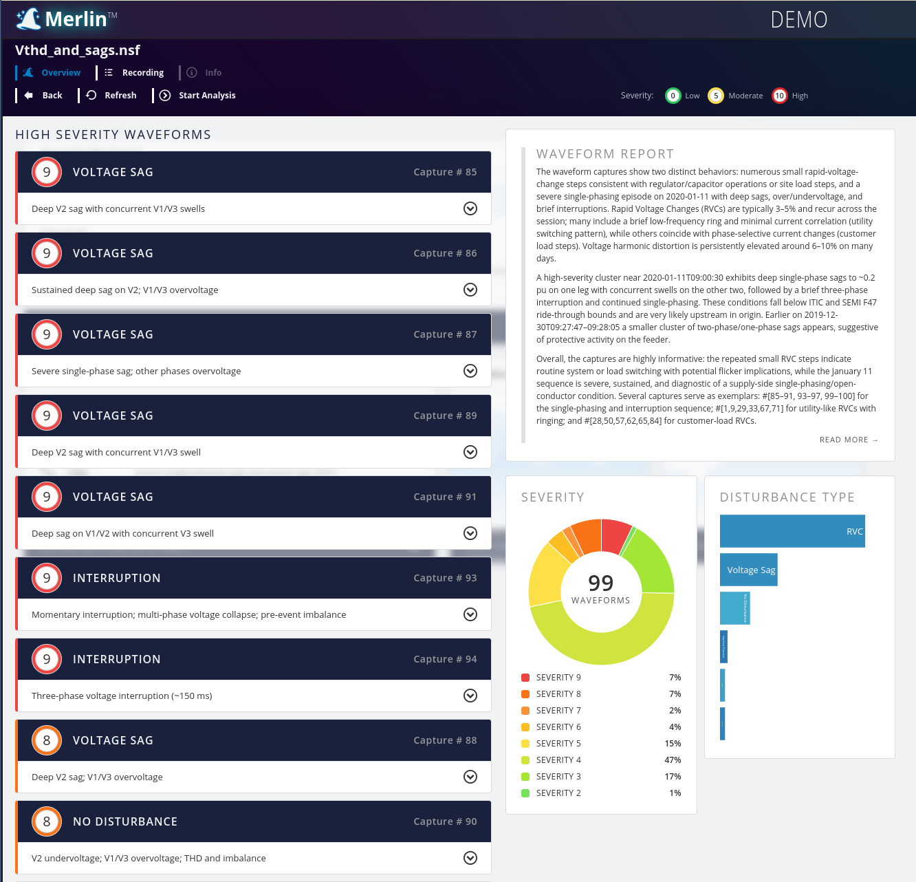
Merlin™ will perform a series of analyses (in parallel across the waveforms captured in the recording), assign a severity (0 through 10) for each captured waveform and then provide a summary of its analysis for each waveform as well. When the analysis is complete, the investigator is presented with a list of the most important waveforms first (ranked by severity) and is given a short, one paragraph overview of all of the recordings in the session, accompanied by a bar graph breaking out the waveforms into severity bins. See Figure 1 for an example.
The one paragraph summary at the top right of the screen is the Waveform Report.
If the user clicks on the box that contains the overview, the full Waveform Analysis report is launched. This is a much more detailed report that provides insight into the recording as a whole. Trends that are discovered over the course of several hours (or even days or weeks) are picked up and identified in this report with supporting references to individual captures within the recording.
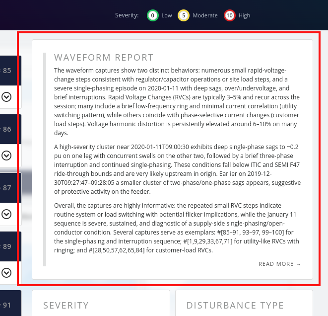
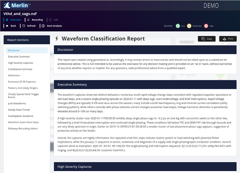
Figure 3. Waveform Report
Ranked Waveform Capture List in Merlin™
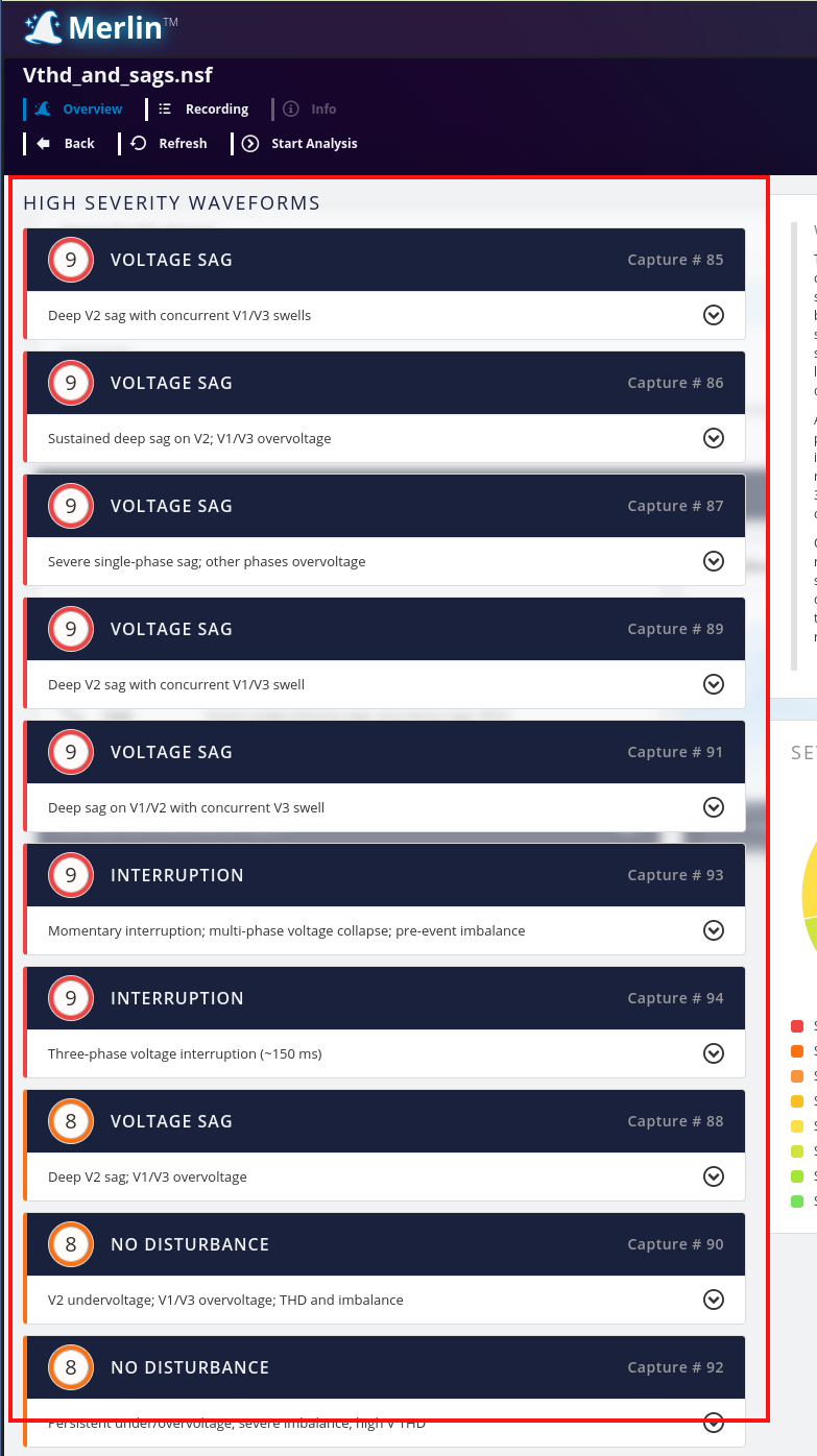
The overview page that the user first sees upon entering the waveform analysis section of a Merlin™ report is concise. As mentioned above, there is the Waveform Report at the top right, a pie chart that shows an organized and quantized count of waveforms by severity and then, on the left-hand side of the screen, is the full, sorted (by severity) list of each individual waveform that was captured in the recording.
Note that each waveform element in the list has the following elements:
- A one-line description of the capture
- A severity score
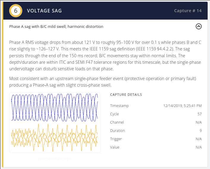
If the user clicks on an individual waveform, the analysis window expands to show a more detailed overview of that specific waveform.
This view provides three individual segments:
- The topmost segment contains the detailed analysis of this individual waveform. Usually two to three sentences in length, it highlights power quality disturbances (if present) and lets the investigator know if there are any standards excursions in the capture.
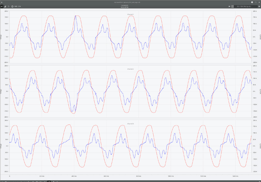
- On the bottom left the user finds a preview of the waveform capture itself. It does not contain tremendous detail, but does show the capture preview with voltage phases grouped on the top plot and current phases grouped on the bottom plot. The user can click on this graph to be taken into the detailed waveform capture analysis tools provided within PQ Canvass.
- The bottom right segment of the overview contains the metadata for the waveform capture itself. Information such as the timestamp, trigger reason (wave shape, RMS variance, etc.) and the cycle number within the second at which point the capture was triggered.
What Types of Disturbances Does Merlin™ Look For?
Triggered waveform captures are great for capturing transient, short-duration (sub-second) disturbances and that is where Merlin™ really shines. (It is worth noting that Merlin™ does analyze periodic captures and provides an overview in the Waveform Report of the steady state of the system.)
While not a definitive list (mostly because this list continues to grow as we add more features and analysis tools to Merlin™), the following classes of disturbances are analyzed and reported on:
- Rapid Voltage Change
- Voltage Sags and Swells
- Harmonic Distortion
- Interruptions
- Time-of-Day and Time-of-Week Correlation
- As part of the Waveform Report, trends that may not be noticed with a manual investigation of the waveforms or stripcharts are highlighted in order to help identify root causes.
- Generic Pattern Recognition
- If there are distinct load patterns within a recording, those loads are isolated and identified as being distinct loads. While the specific load itself isn’t identified (ex. “compressor”, “motor start”, etc.), load signatures are reported on as being distinct loads based on characteristics.
- Root Cause Identification
- Common root causes are identified, such as inrush current leading to a voltage sag or recloser operations, etc.
Conclusion
While Merlin™ is in its infancy, it is still remarkably powerful. The waveform analysis capabilities of Merlin™ are industry-leading and genuine time savers. As PMI continues to refine and develop Merlin™ these features and areas of analysis will only continue to improve.
Demo
If you would like to see a live demonstration of Merlin™, please follow this link to sign up.