
Abstract
In September of 2017 a homeowner discovered that his well was not delivering water. The suspicion was that the pump itself was in some way failing – perhaps the motor had failed, or there was a mechanical problem with the motor or piping. A Boomerang was installed to investigate, and left in place to confirm proper operation after the problem was fixed. This white paper illustrates how a Boomerang was used to help identify the cause of (and solution to) the well pump issue, and also describe how to make use of Canvass to give email/SMS notifications in case of equipment failure.
How the Boomerang Works
The Boomerang is designed for long-term installation – typically a user would place a Boomerang on a power pole, in a transformer enclosure, or in-line with a Form 2S revenue meter. The Boomerang then takes continuous one-second measurements and sends them back into PMI’s Canvass web service where all data is permanently stored and can be retrieved and analyzed by a user using a web browser. (Note that the Boomerang comes in several configurations and form-factors, from single phase 120V plug-in units, to three phase pole-mount units capable of measuring voltage, current and power).
The Boomerang – which is a “long-term” recording device – isn’t typically thought of as a “spot-measurement” tool that can be used to diagnose equipment failure. However, as shown below, a permanently installed Boomerang is great at detecting variations in load patterns and even, in some cases, detecting equipment failure. In this particular case, the Boomerang was connected to the well pump and allowed to report in for several hours so that an accurate diagnosis could be made.
It is also worth mentioning that since the recorder connects to Canvass with a cellular modem – there is no need to retrieve the device and “download” recording data from it – the voltage and current is available from within the Canvass web application within minutes of powering up the unit.
Observations
After installing the Boomerang and allowing it to register data for a period of time some observations were made.
Figure 1 shows the first measurements of current taken by the device. The first thing to jump out is the continuous nature of the amperage readings – steady at approximately 8A over a period of approximately 15 hours. This pump should only be operating as needed (a pressure sensor connected to a water tank enables the pump as water is drawn from the tank). The continuous current consumed by the motor indicates a problem.
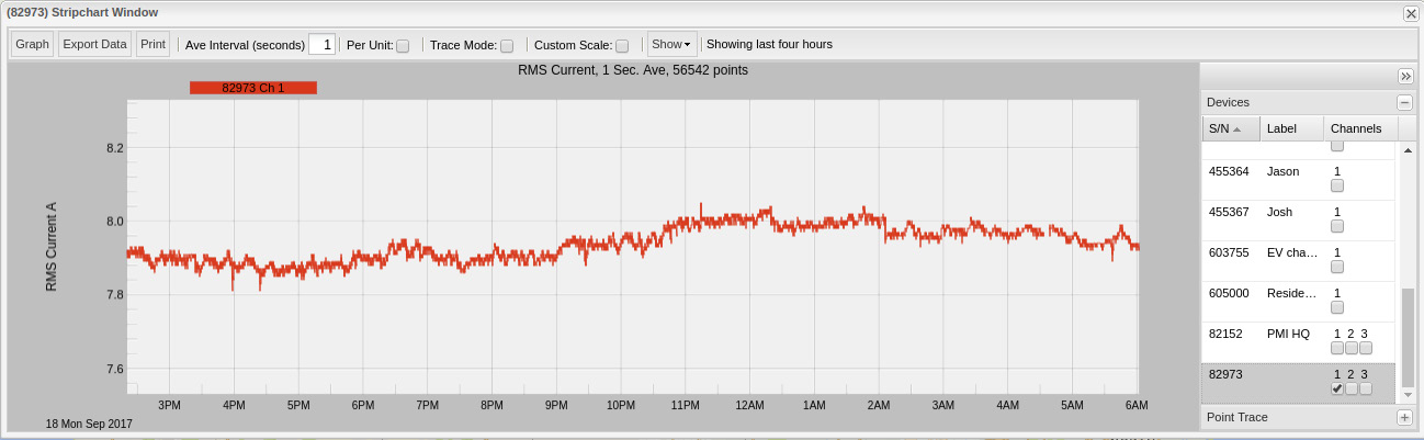
The motor in question is a single phase, one horsepower (1 HP) motor running at 240V. A quick lookup for expected current draw for a 1HP single phase 240V motor is 8A – which puts the measurements spot on with the expected draw.
Resolution
After reviewing the measurements from the Boomerang it was determined that – given the motor type and horsepower – the current draw was within a reasonable and expected range. Since the pump motor is drawing the correct current, running continuously, but no water is produced, a mechanical issue is likely.
The eventual cause was determined to be a broken pipe – the pressure tank was not full so the pump was running continuously in order to try to refill it, but the pipe to the pump was actually broken resulting in the pump’s inability to refill the tank.
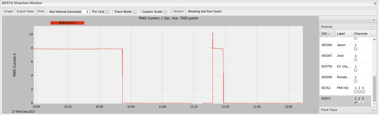
Figure 2 shows the current draw after the pump was repaired. Current drop from the continuous 8A reading at about 10:40 and remains off for the duration of the repair – approximately 45 minutes. The motor kicks back on around 11:25, runs at approximately 8A for 5 minutes until the tank is full and then shuts off.
Methods for Early Detection
Now that a Boomerang has been installed on the well pump and some long-term readings have been made, the Boomerang can be configured to alert under anomalous conditions. (For those installing and maintaining well pumps, Boomerangs can be deployed in both existing and new installations and configured to alert under anomalous conditions as well.)
Figure 3 shows an approximately one-month duration current reading for the Boomerang installed at the well pump. What becomes abundantly clear is that the pump is not running continuously – in fact, an entire week goes by without the pump kicking on even once.
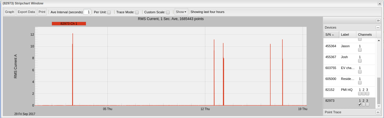
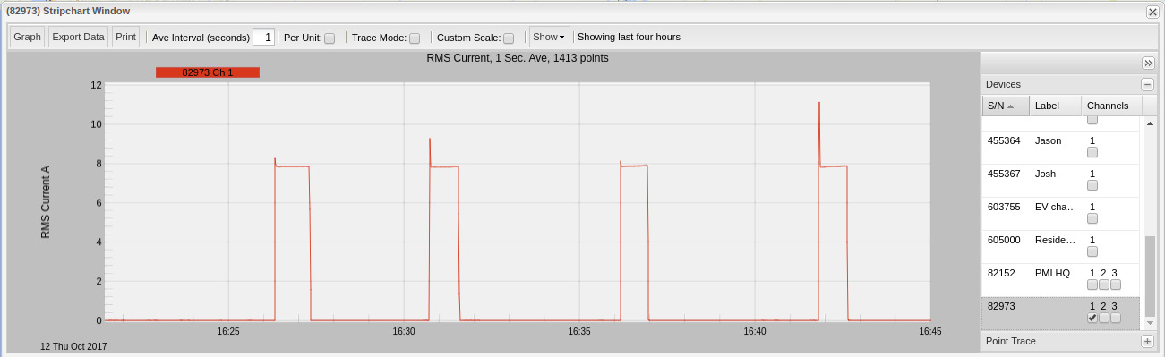
Figure 4 shows a 25-minute capture of the Boomerang’s current readings. What can be seen are a series of four short, one-minute-or-less-in-duration spikes where the pump is being run. This is a reasonable baseline average for run-time and for current readings.
Using this baseline information the Boomerang can now be configured to send alerts to a user (pump installer, maintenance technician, etc.) when anomalous readings are made.
In this particular case, the author recommends setting a current high threshold of 7A with a holdoff time of 400 seconds (8 minutes). As was seen under “Resolution” above, the pump ended up running for approximately 5 minutes to refill the tank when the tank was low (or empty). Setting a holdoff time to 8 minutes will prevent a “false-positive” triggering in the event that it takes longer to fill a (potentially larger) tank from empty on new installations, but will alert when a similar condition to the burst pipe occurs again: after 8 minutes of running continuously at 7A the user will be alerted.
Conclusion
The installation of a Boomerang allowed for an accurate diagnosis to be made on irksome problem. By deploying a Boomerang in existing and new equipment installations, technicians and owners can be notified of failing equipment and systems much earlier by email or SMS alert, with important troubleshooting data available in web browser.