
Abstract
Sometimes when hooking up CTs for a device, a user will inadvertently place the CTs in the wrong configuration. Maybe the channel 2 CT was placed on the third phase and the channel 3 CT was placed on the second phase? Maybe one of the CTs was placed backwards, so the power readings for that phase are inverted? This can be an annoying and time-consuming problem to troubleshoot and correct, and meanwhile, all the data you’re getting back isn’t being measured how you actually wanted it.
The Problem
Currently, somebody has to go out into the field to correct the hookup physically. This involves the inherent risk of shock when changing the hookup to the desired one. With CTs hooked up incorrectly, readings such as real, reactive, and apparent power will be incorrect. Symmetrical components, power factor, and distortion power factor calculations will be wrong as well.
The Solution
Clearly, a solution is needed that eliminates the extra risk, reduces man-hours spent correcting a CT hookup, and that ensures that the correct data is recorded in the manner the user intended. Fortunately, an incorrect CT hookup can be adjusted logically inside the Bolt itself, while still providing users with the flexibility to hook up their devices in whatever configuration they desire. We came up with the ‘Phase Correction’ feature that makes fixing an incorrect CT hookup a simple click of a button. This can be done in the field using the PMI View iOS app, or from the comfort of your office via a network connection.
When initializing an applicable device, such as a Bolt, users can select a “Phase Correction” mode from the following list:
- Disabled (default)
- Automatic
- Manual
Disabled Mode
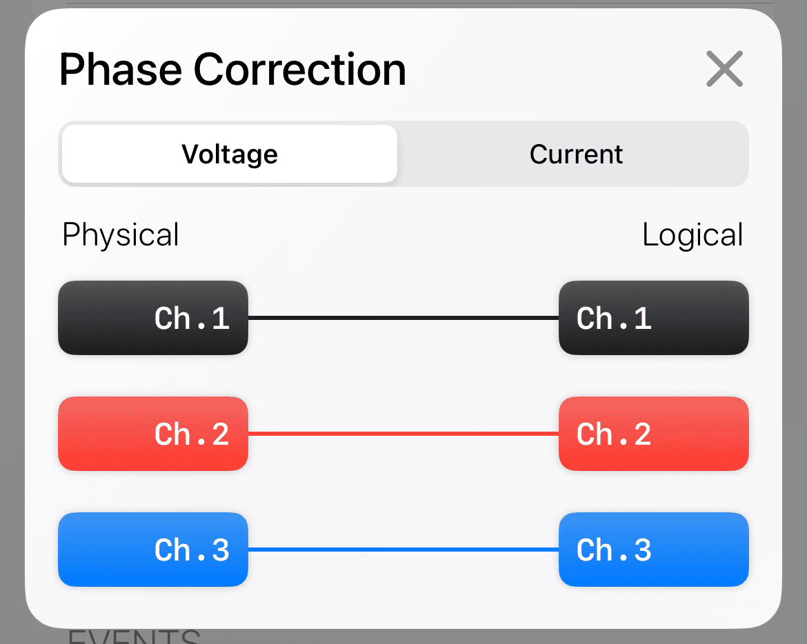
This is the default mode, and it allows users to use the physical hookup as is. I.e. if the channel 1 CT is hooked to channel 2, then that is what is measured for channel 1.
The phase adjustment mapping for this mode will look like the following:
Auto-Fix Mode
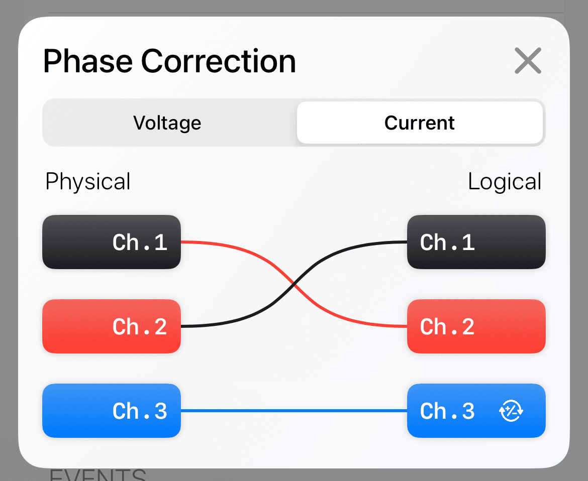
This mode will attempt to determine if the physical hookup is wrong, and will perform a logical swap or invert the polarity of channels as necessary. This auto-correction happens at the end of the recording initialization countdown. During the countdown, the physical hookup is used for measurements. This is how we determine what needs to be adjusted, if anything.
The following mapping shows the adjustment for a device who’s channel 1 and 2 CTs were swapped, and who’s channel 3 CT was inverted.
Manual Mode
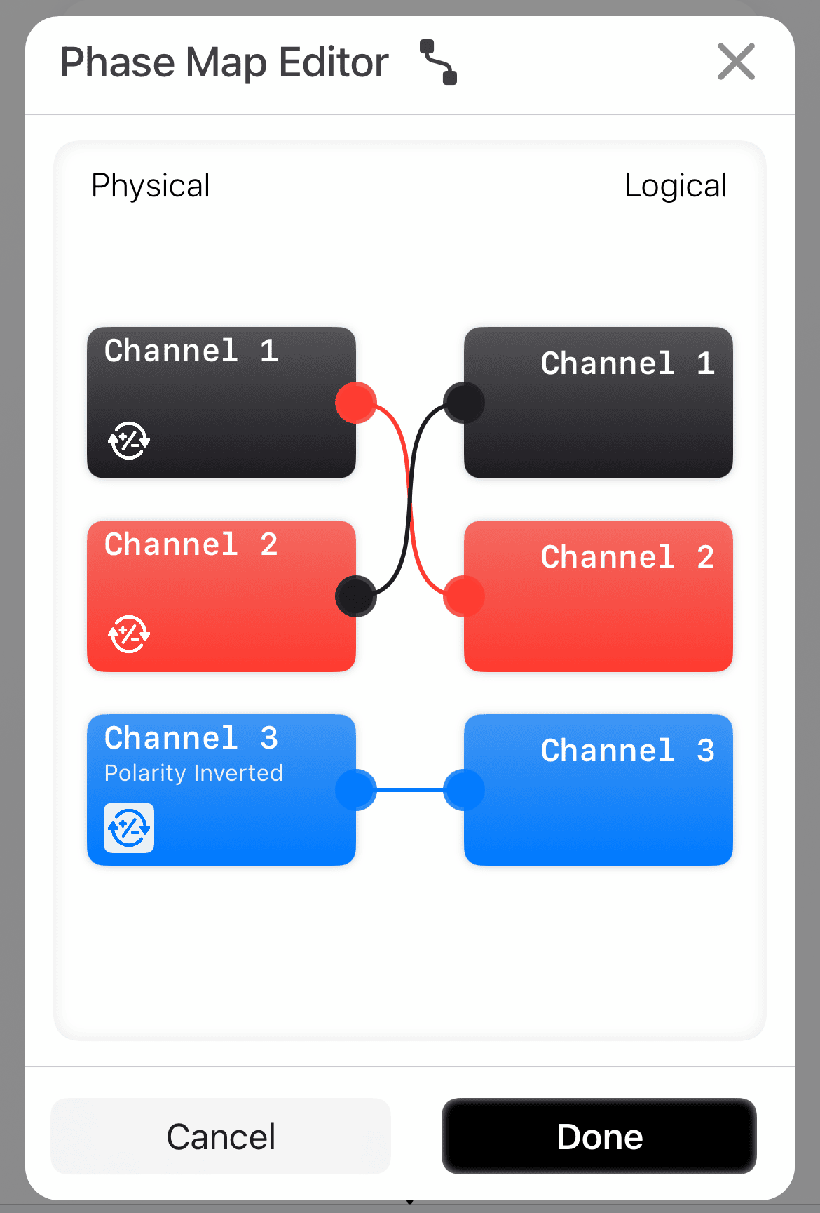
This mode allows the user to specify a logical arrangement of the channels and their inversion. Simply drag channels from the left side (physical) to the desired channel on the right (logical). Selecting the “Invert” button will reverse the polarity for a physical channel. The user-defined mapping is applied at the start of the recording initialization countdown.
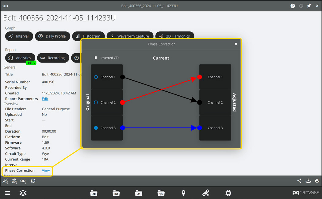
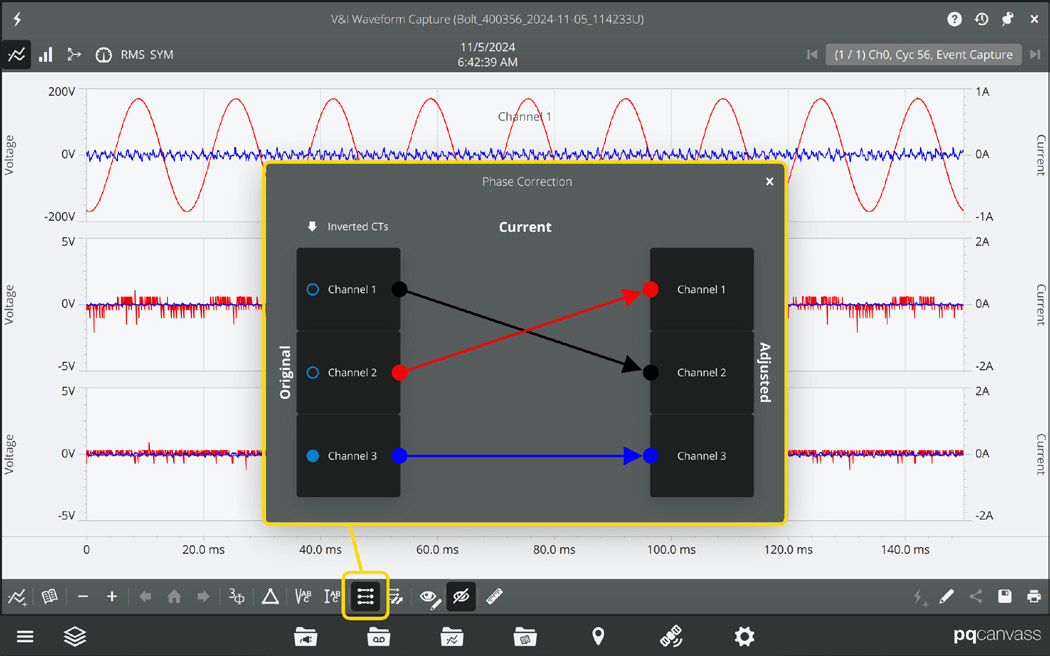
In the following example, the user has accidentally hooked the channel 1 CT around the second phase, the channel 2 CT around the first phase, and the channel 3 CT around the third phase, but put the channel 3 CT on backwards. They have chosen to re-initialize their recording using the manual mode, with physical channel 1 mapped to logical channel 2, physical channel 2 mapped to logical channel 1, and inverted the polarity on channel 3. This will make their recorded data match their intended hookup of channel 1 to channel 1, channel 2 to channel 2, and channel 3 to channel 3.
One instance in which the manual map mode may be used is where a breaker is open during installation. If the auto-adjustment cannot sense current in a CT, then the correction algorithm cannot properly make recommendations. Once the breaker is closed, however, it may become apparent that the CTs have been improperly installed. It is at this time that the user has the ability to manually correct the installation from PQ Canvass or PMI View. Note that the user can also select “auto-detect” again and re-initialize the recording. This will allow the Bolt itself to recommend corrective action (if necessary).
As described in the following sections, users can view what phase correction mapping is being used on the device as well as toggle viewing certain recorded data as mapped and as the physical hookup.
Initializing Phase Correction
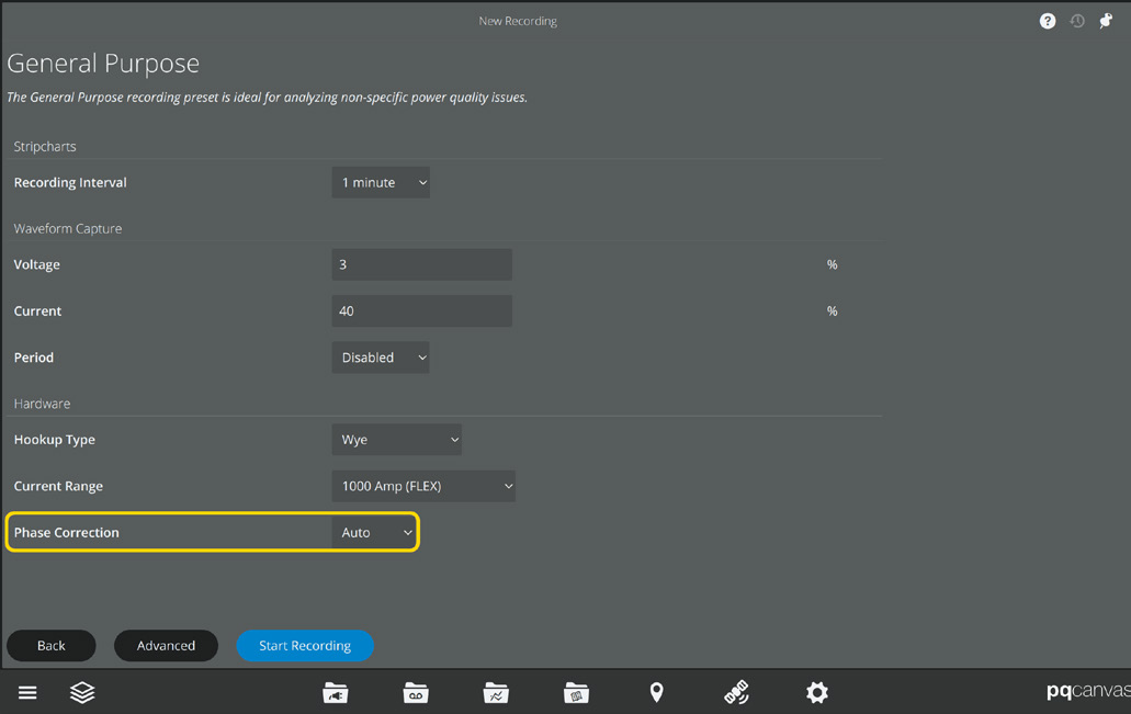
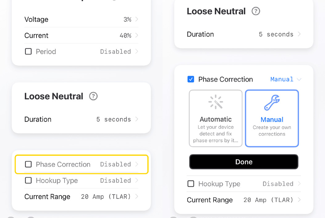
When initializing a recording in PQ Canvass or PMI View, you can select a phase correction mode, as seen in the following screenshots.
Viewing Phase Correction
In PQ Canvass you can view the phase correction mapping used for a recording, based on which phase correction mode you selected. The mapping can be viewed by selecting the “View” button next to “Phase Correction” in the recording’s header report.
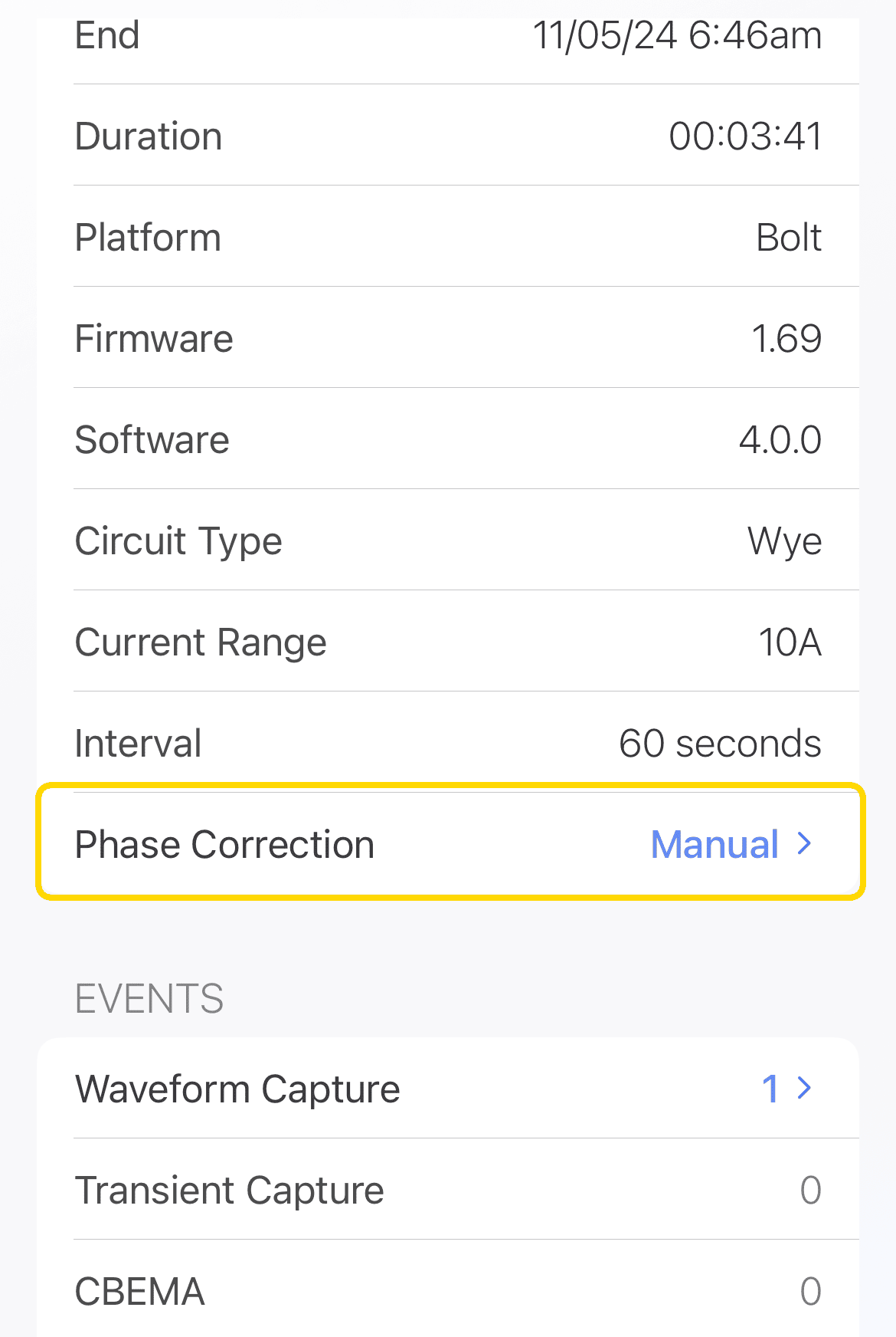
In PMI View, after downloading a recording, you can view the phase correction mapping used for that recording, based on which phase correction mode you selected. The mapping can be viewed by selecting the “Phase Correction” in the recording’s header report.
Toggling Phase Correction
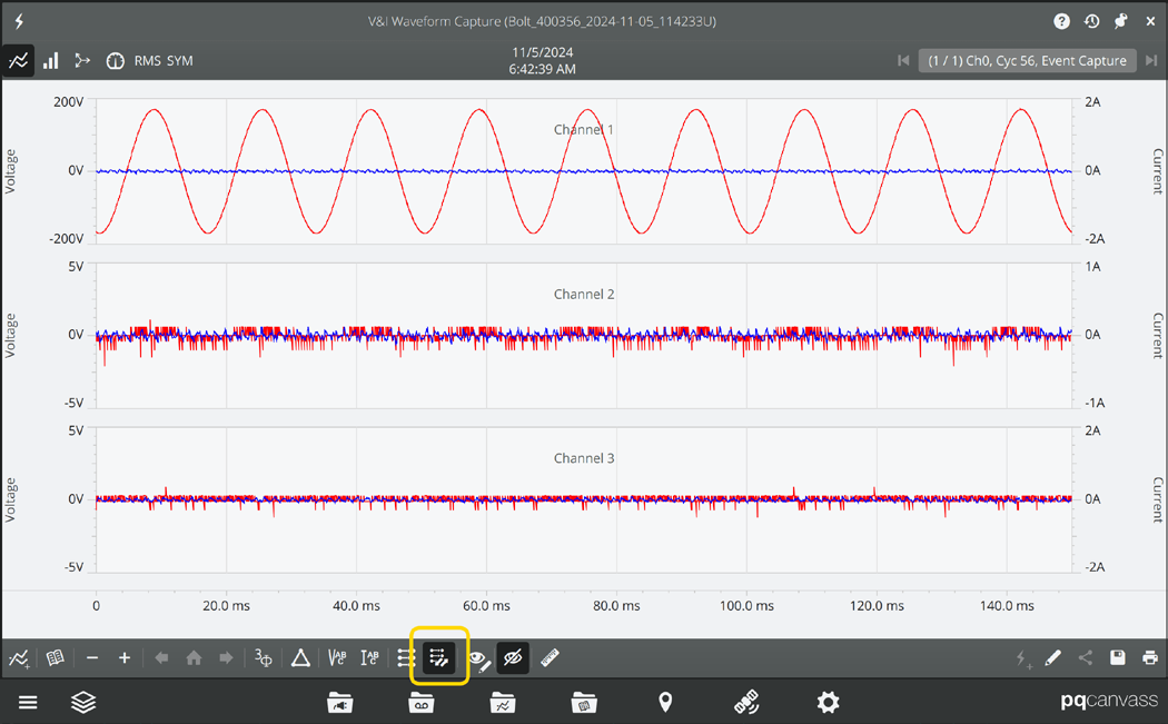
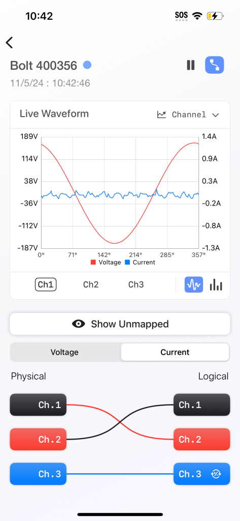
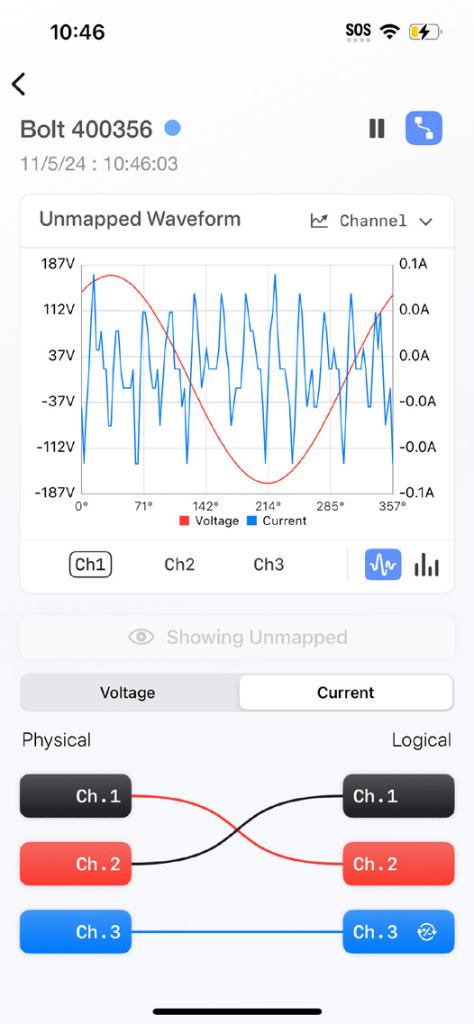
When viewing live data for a recorder—waveforms, vector diagrams, and meter data—you can select a toggle button which will display the same data using the physical hookup instead of the configured phase correction mapping. On PMI View, the toggle button requires a press and hold, and will un-toggle when released.
If you selected “disabled” mode or “manual” with no changes from the physical hookup, then you will see no changes when toggling the display. You can also toggle the phase correction mapping for recorded waveforms.
Hookup Validation
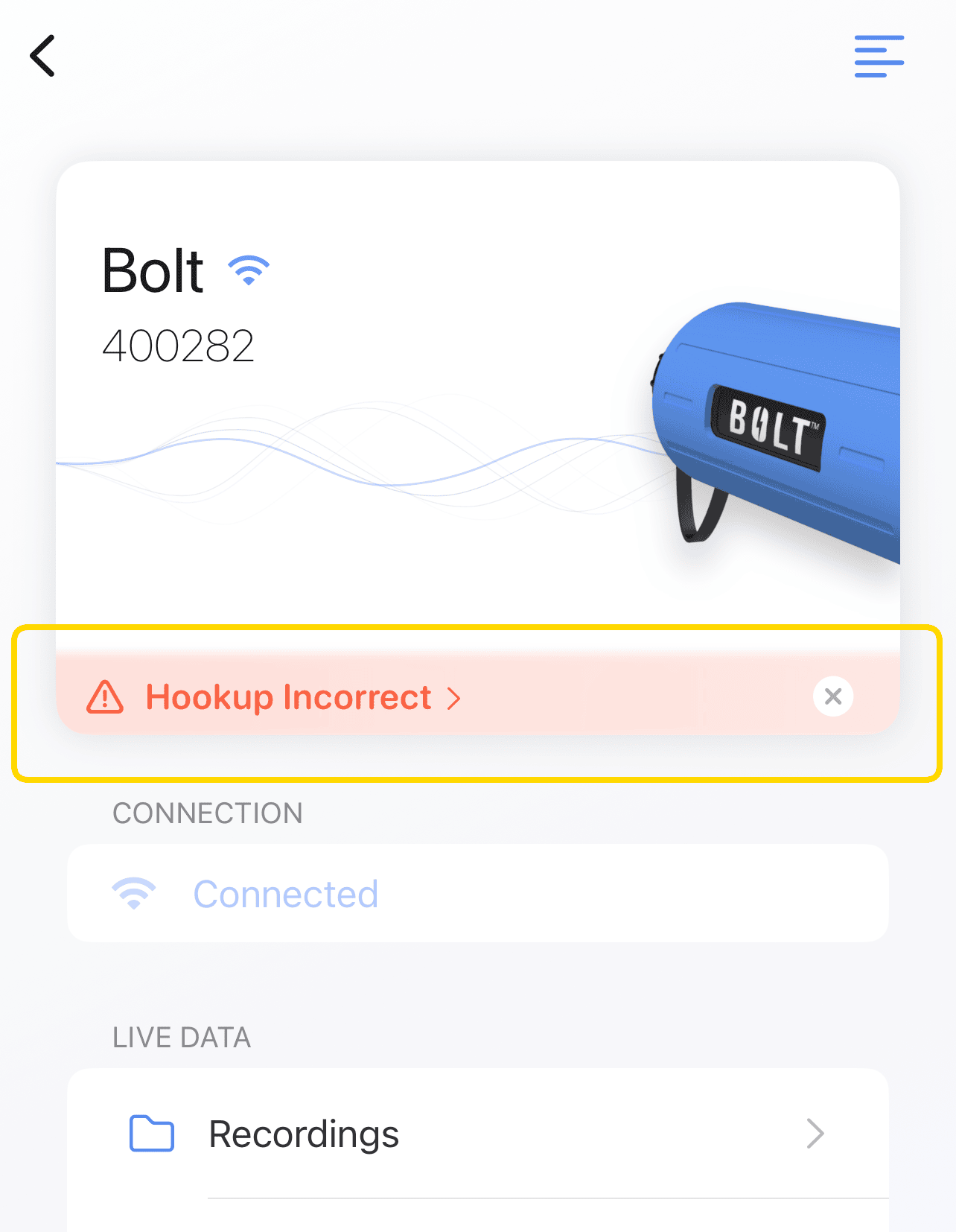
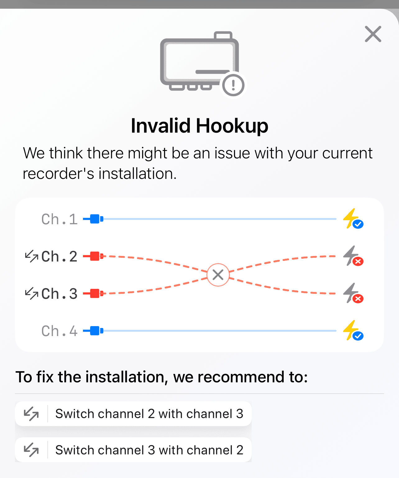
PMI View has the additional feature of being able to auto-detect issues with your hookup. This analyzes live waveform data to determine if any CTs are hooked up wrong. If any issues are detected, a notification appears. When clicked, the notification will display a suggestion on how to correct the hookup. This could be performed physically or by re-initializing with a manual phase correction map configured in the suggested way. You could also re-initialize with the automatic phase correction mode, which is usually the best choice.
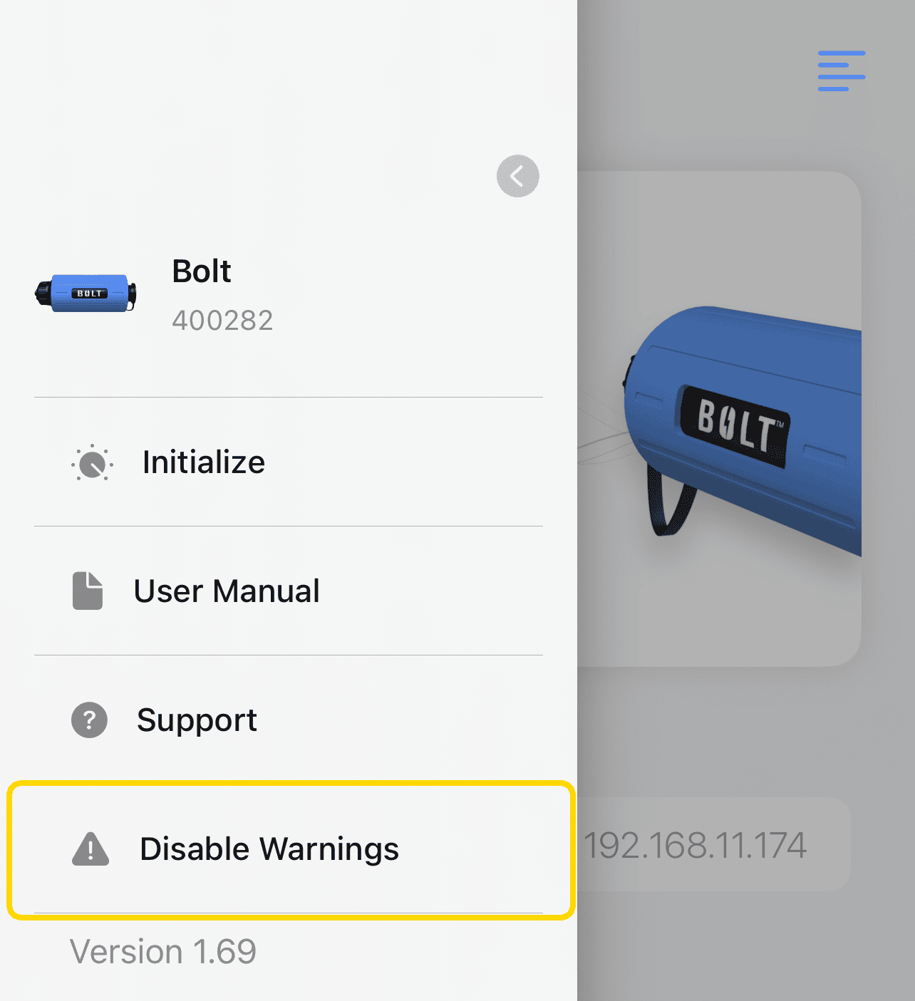
If you don’t wish to see those warnings for a device, simply open the left-hand menu and select “Disable Warnings”. You can always turn them back on again later.
Conclusion
If a recorder was hooked up incorrectly, you no longer have to waste time and effort correcting it. Simply select the “auto-fix” phase correction mode when you initialize your recorder. If you need a specific configuration or if you wish to override an auto-correction, simply select “manual” and configure your desired mapping.