Abstract
Impact loads are frequent and very high current surges which are usually greater than the rating of the transformer on which they occur. They present as repeated near-short circuit conditions, but aren’t enough to trip a fail-safe for the system. Continuously subjecting a transformer to above-rating levels of current for what may seem like short periods of time, seconds to minutes, is enough to significantly compromise the reliability and lifespan of the transformer. Each and every time a sudden inrush of current exceeds the rating of the transformer, damage to the internals of the transformer can occur.
Causes
There can be several reasons that impact loads may occur. Equipment that has a very large starting current compared to its running current, such as very large motors, can cause these impact loads to occur. Motors that don’t have Variable Frequency Drives (VFDs) or Soft Starters are most likely to cause loads with high inrush current draws.
This can be an issue with unit transformers dedicated to a single load sized specifically for the steady state load current. Only taking into account the steady state current draw of a motor, and not the amount of current needed to start one up, is a prime example of this.
However, impact loads may also happen when a large enough quantity of equipment have their inrush current draw synchronized. Many motors on a conveyer belt system that all start and stop at the same time in a factory is a good example of this. Most often there is an expectation of load diversity, where motors will be starting and stopping at random but not all at once, and the transformer is rated for the steady state of most of the motors or equipment present.
Any time a load has a very high peak compared to its average RMS current draw, and it occurs frequently, one should be mindful of the effects this can have on transformers, the connected equipment, or the system altogether.
Issues
Since transformers have a maximum current rating, any time this is exceeded can be detrimental to its lifespan and performance. These large spikes in current also cause large magnetic forces to occur, which cause heavy mechanical stress on the windings and core of the transformer.
Decreases in voltage due to the current spikes can cause equipment that must run on a steady-state supply of voltage to have a loss of performance, disruption, or to incur damage.
Transformers are crucial to the continued and uninterrupted use of equipment for many industries and businesses. Any time a transformer fails is an inopportune time, so it is important to detect and mitigate or prevent failures.
Detecting
When looking for impact loads, pay attention to large differences between frequent peaks in current versus the average. One’s first inclination may be to assume that harmonics were the cause of the transformer failure, but note that both voltage THD and current THD may be low and waveforms occurring during that period may also look normal and sinusoidal, so they may not be a good indicator that there are no stressors on the transformer.
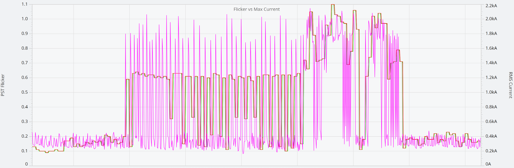
High Flicker (> 1.0 Pst) during periods of frequent and repeated current spiking due to voltage sags can also be indicative of impact loads occurring.
Taking the sum of the Apparent Power across all 3 phases will give you the amount of VA the transformer is being subjected to during these pulses. The number of times these pulses occur within a period of time is crucial to determining whether the transformer can handle them. In the section Mitigating, further details about these pulses, time frames, and determining the susceptibility of a transformer to premature failure are presented.
Detecting these occurrences in PQ Canvass, our web-based power quality analysis suite, is as simple as opening the device’s recording, and opening a measure in the graph type of your choice.
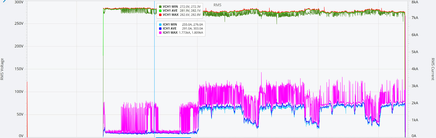
In this recording, we can see the disparity between the average current and maximum current quite easily in its stripchart data. The jump from the steady state (average) current to its peak inrush (maximum) current illustrates these impact loads. When setting up a recording, make sure that the average and maximum values are to be recorded, and that RMS Current (and RMS Voltage) measures are enabled.
Due to the rapid increase in current, the corresponding voltage sag can be seen in a Pst flicker graph. These fluctuations in flicker are occurring several times an hour in this example. To see this data in a recording, Pst Flicker and RMS Current must have their average and maximum values recording.
Analyzing the waveform data can also be indicative of sudden high inrush currents. In this same recording, there is a waveform capture that occurred and we see an increase of the magnitude in current happening at that moment.
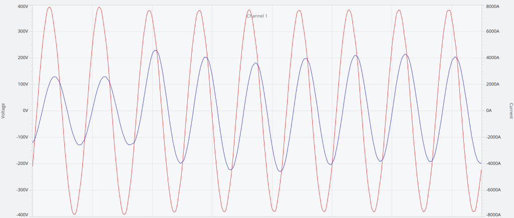
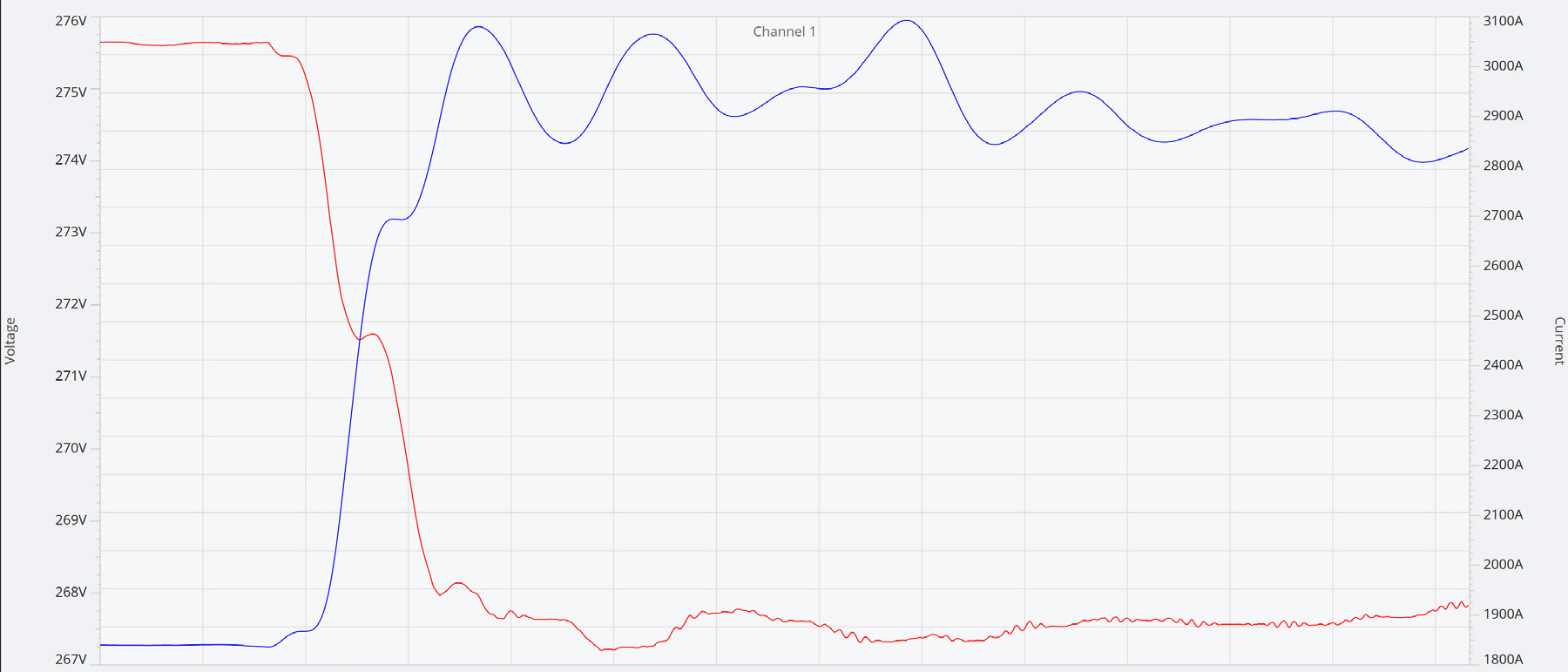
From this same waveform capture, we can translate its waveform data into an RMS representation, and we can see the increase of current from around 1900A to around 3100A.
Mitigating
The transformer may need to be de-rated to handle the sudden spikes of inrush current. Choosing a transformer with a higher rating than what would be used for the steady state current will help to prevent the transformer from being damaged during any such events.
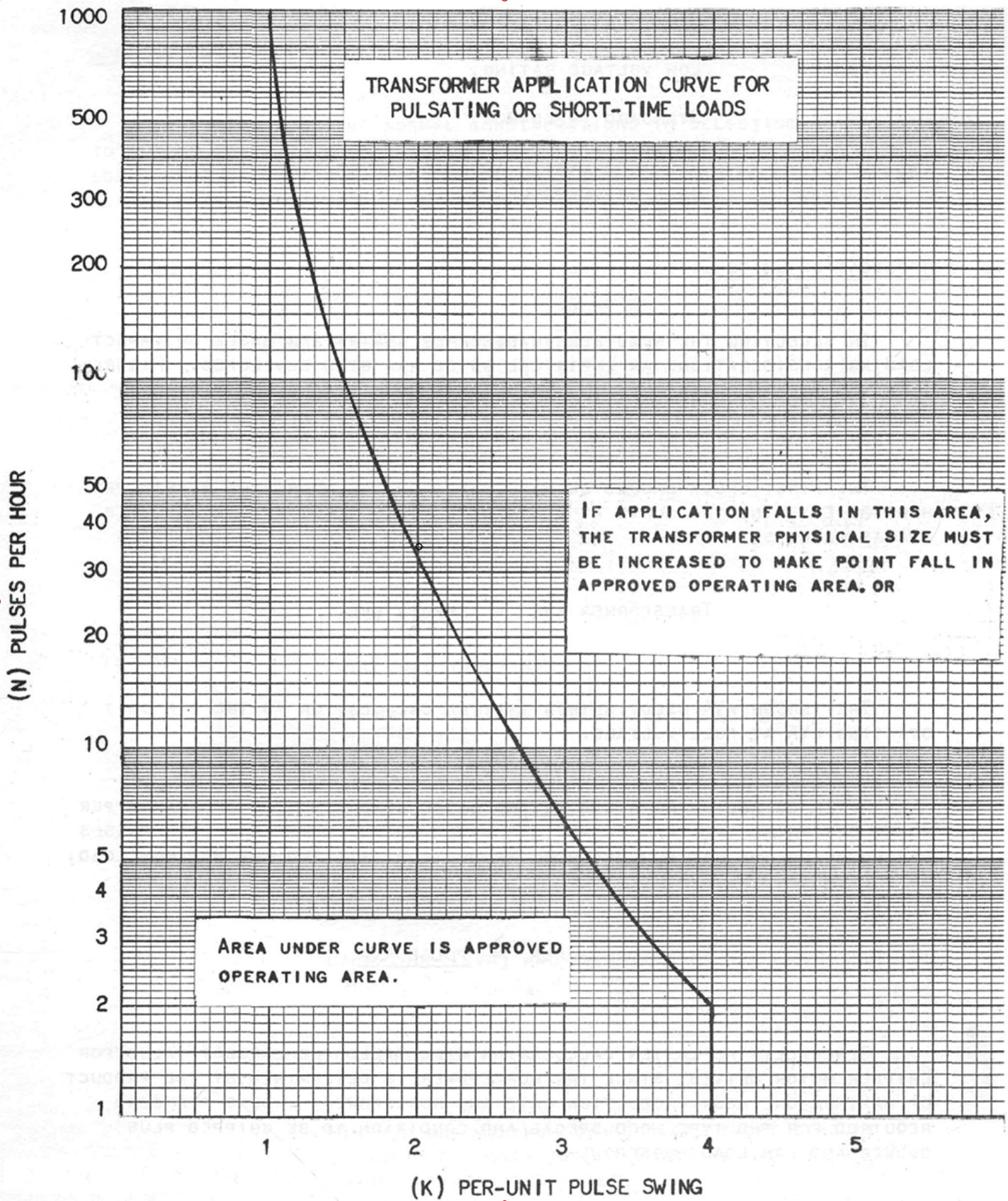
The rate of pulsing that occurs needs to be taken into account too, as the more pulses that occur, the higher the rating the transformer needs to be. Frank J. McCann and Robert J. Ristow of the General Electric Company presented a paper at an IEEE conference, “Problems of Impact Loading on Unit Transformers”, that details a graph and equations to determine whether a transformer with a certain rating will be able to handle these high load pulses within an hours time. Anything falling under the curve has been deemed an “approved operating area.” This has been the de-facto guide for dealing with impact loads and appropriately determining if a transformer is being subjected to more than it has been deemed capable of handling.
Looking at the following graph, one can determine whether their transformer will be resistant to a given number of pulses in an hour long span of time by determining K for their system and transformer (Figure 5).
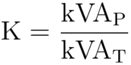
Where kVAP is the inrush pulse, and kVAT is the KVA rating of the transformer, one can calculate the “pulse swing” K needed to determine if the transformer being subjected to N pulses per hour can handle these short-term high impact loads.
Careful examination and forethought of the needs of the system will save money and can prevent or reduce downtime.
Conclusion
Selecting transformers with the proper kVA rating is not just about the amount of steady state current that the transformer can handle, but also anticipating any spikes caused by the inrush of current needed to start equipment. De-rating a transformer will give the breathing room necessary to deal with these sudden impact load demands on an electrical system. Accounting for these variations in current draw will decrease the likelihood of a transformer failing much sooner than it was designed for.