Introduction
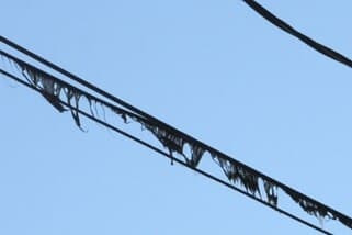
A loose neutral condition happens when somewhere between the line transformer secondary and the meter base, the neutral conductor either breaks connection or corrodes to the point that the impedance is several orders of magnitude higher than it should be. If this problem happens to one of the hot legs, it is not a particularly interesting problem because everything downstream of the break simply turns off until the repair is performed. However, a break in the neutral wire can cause large voltage sags and swells, as well as some other strange effects.
Description of Problem
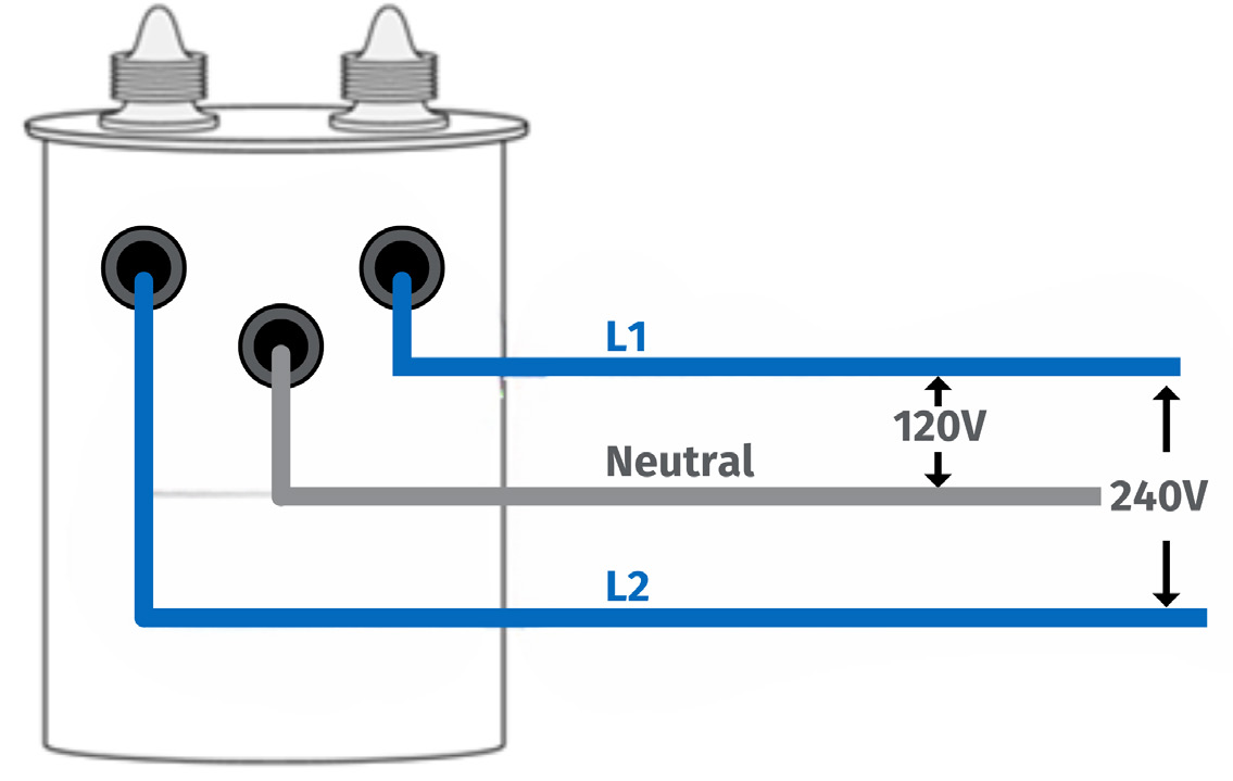
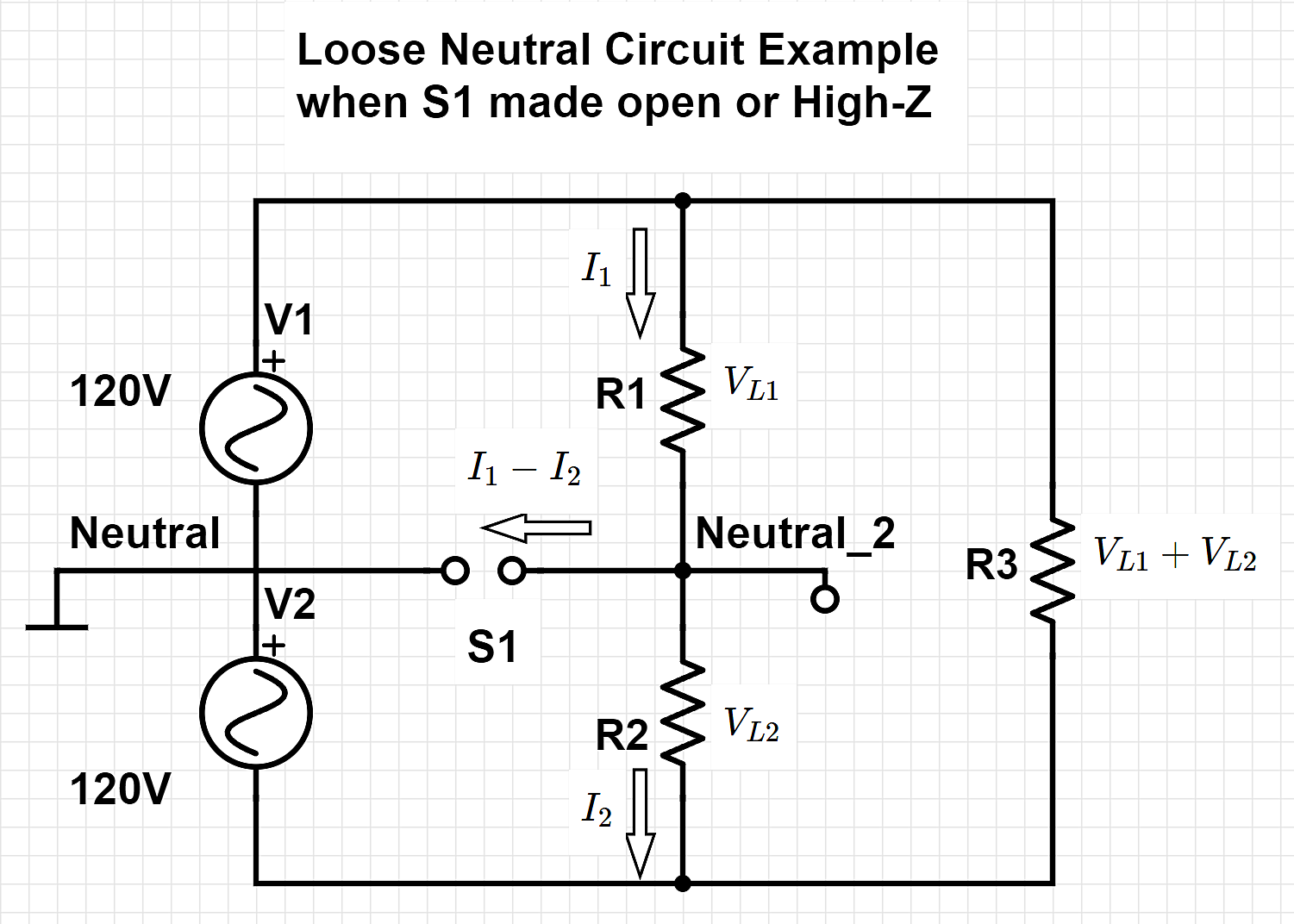
Figure 1 shows the typical house connections to the line transformer. In this configuration, there are two 120V RMS signal and a neutral conductor. The two hot wires are out of phase with each other so their difference is a 240V RMS signal. Normal wall outlets are connected to one hot wire and to the neutral wire and large appliance outlets are connected across the two hot wires. Figure 2 shows the equivalent circuit diagram of a typical house, where R1 represents the parallel load from V1 to neutral, R2 represents the parallel load from V2 to neutral, and R3 represents the parallel load from V1 to V2. Ordinarily S1 is closed, but when it is opened, suddenly R1 and R2 form a voltage divider circuit, where before they were relatively independent of each other.
Before Break:

After Break:

The voltage across the R3 load is completely unaffected by S1 opening, but the voltages across R1 and R2 depend on how unbalanced these loads are.
One important thing to notice is that before the break:

And after the break:

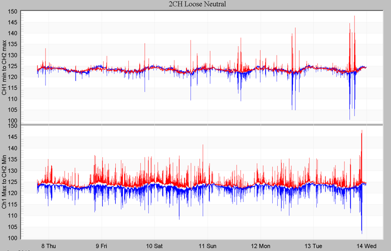
This sum remaining constant implies that whenever one leg swells, the other leg must sag an equal amount. This is in fact the principal way that we are able to determine that a loose neutral condition has occurred. Figure 3 shows a week long recording of a house’s power signal that is clearly experiencing a loose neutral problem.
Mathematical Description of Loose Neutral Effects
Define the load ratio:

and assume that

Then, after the neutral conductor breaks, the new voltages become

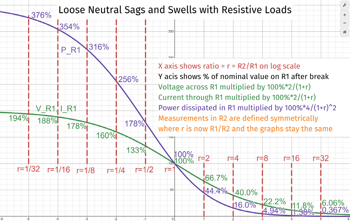
Because of Ohm’s Law, V = I • R, the new currents in each leg are scaled proportional to the voltages, which implies that the power dissipated in each leg is scaled by that same factor squared. Figure 4 shows these scaling factors for voltage, current, and power. As an example, suppose that

implying that

Before the break occurs,


After the Neutral break, we can look at the figure 4 graph with r = 4 to see that the voltage across and the current through R1 is 40% of the nominal value and the power dissipated is only 16% of nominal.

To see the effect on R2, the r = 1/4 point on the Figure 4 graph shows that the voltage across and the current through R2 is 160% of nominal and the power dissipated is 256% of nominal.

This sudden jump from dissipating 30W up to 76.8W is more than enough to cause equipment failure and possibly start a house fire.
Symptoms of a Loose Neutral
In a multipoint grounded system, it is possible for the neutral current to flow through the ground. Due to the finite ground resistance, a noticeable voltage can be detected on grounded objects. Alternatively, it is possible for the neutral return current to flow through the braid of a CATV coax cable to a neighbor’s house and then to the neighbor’s neutral return. Figure 5 shows this dangerous symptom in action.
Often one of the first concerns that customers notice is that systems that are designed to react smartly to power surges or outages, such as universal power supplies or solar arrays, randomly and unexplainably react as if that condition had happened. Another main symptom of a loose neutral is that lighting systems suddenly get brighter or dimmer, although this effect can be masked by modern LED drivers which generates an isolated DC supply, electrically separate from the input waveform.
Conclusion
A loose neutral is caused by a disconnection or high corrosion somewhere between the center tap of the transformer and the wall outlet in a house. This disconnection turns two separated and unrelated parallel circuits into a single interrelated voltage divider circuit. This condition is dangerous and can cause a large number of problems, including flickering lights, misoperation of machinery, equipment damage, or even house fires. The principal way this condition is diagnosed is that a voltage swell on one leg of the circuit is matched by an equal and opposite voltage sag on the other leg.