
Abstract
DNP is the mnemonic for Distributed Network Protocol and it is used to describe a method of communication between various types of data acquisition and control equipment. It plays a crucial role in SCADA systems where it is used for communication between master stations and remote devices. This white paper will discuss basic DNP3 terminology and how it is supported in the Boomerang monitor.
Basic Definition
DNP3 defines the rules (protocol) for computers located in a control center (master) to communicate data and control commands to remotely located devices (outstations). The DNP3 protocol is non-proprietary in that it is freely available for any vendor to utilize so that products from different vendors can work together. This allows the end user customers to make their choices based on product features and functionality versus compatible protocols.
Master Stations and Outstations
As noted above, a DNP3 master station communicates with external devices (i.e. outstations) for two different purposes. The first is for issuing commands to control the various functions of the remotely located devices. Examples include opening or closing of switches or valves, starting or stopping a motor or setting threshold values for monitoring remote events. The second is to retrieve status information and readings gathered by the outstation. Examples include water levels, the on/off state of a switch, motor speed, voltage levels, ambient temperature and just about anything else that could be measured or collected by a device.
A DNP3 outstation is typically a standalone device that is used to monitor and/or control remote equipment or processes. The outstation is used to collect or act on many different sorts of data including on/off (binary) conditions, counters, integer values, whole numbers, etc. The precise meaning of this data is dependent on the type of outstation and the manufacturer. The DNP3 protocol defines a method for mapping the individual pieces of data to object types and data points. This allows a master station to utilize the data correctly.
The SCADA System
Often there are many outstations associated with a single master station and this arrangement forms the basis of a SCADA system. There are other arrangements of master station (or stations) and outstations that are also utilized but the single master with multiple outstations is fairly typical. See Figure 1. The SCADA system master station will typically have a user interface of some sort that correlates its received data into meaningful displays and allows for input from the user to control remote devices.
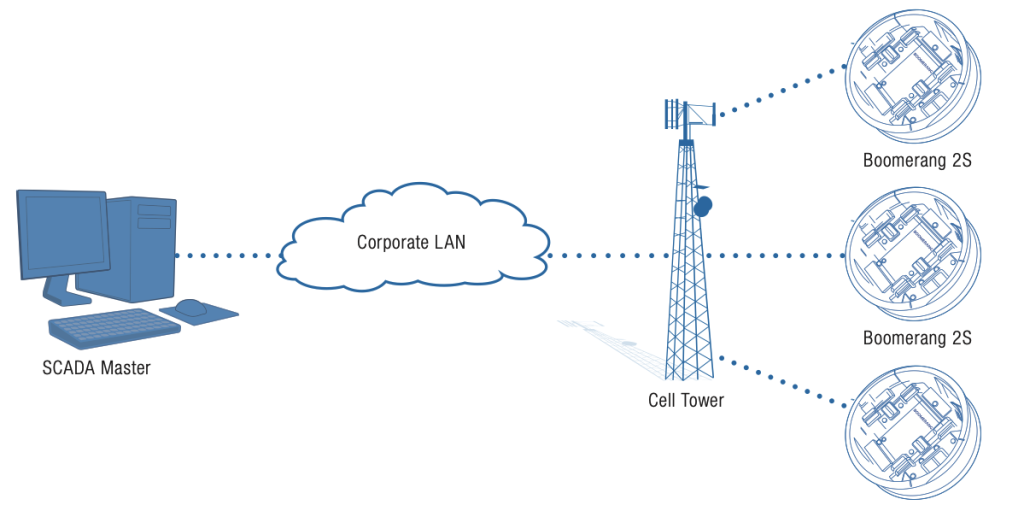
The collection of remote data is accomplished via two distinct modes and these may be utilized separately or together. The first method is for the master station to query or poll the outstations on a periodic basis to collect the most current value of any available readings. The second method is for the outstation to send data as it changes or send notification of changed data to initiate a poll from the master. The exact methods available are dependent on the configuration of and functionality supported by the particular outstation being used.
Boomerang as an Outstation
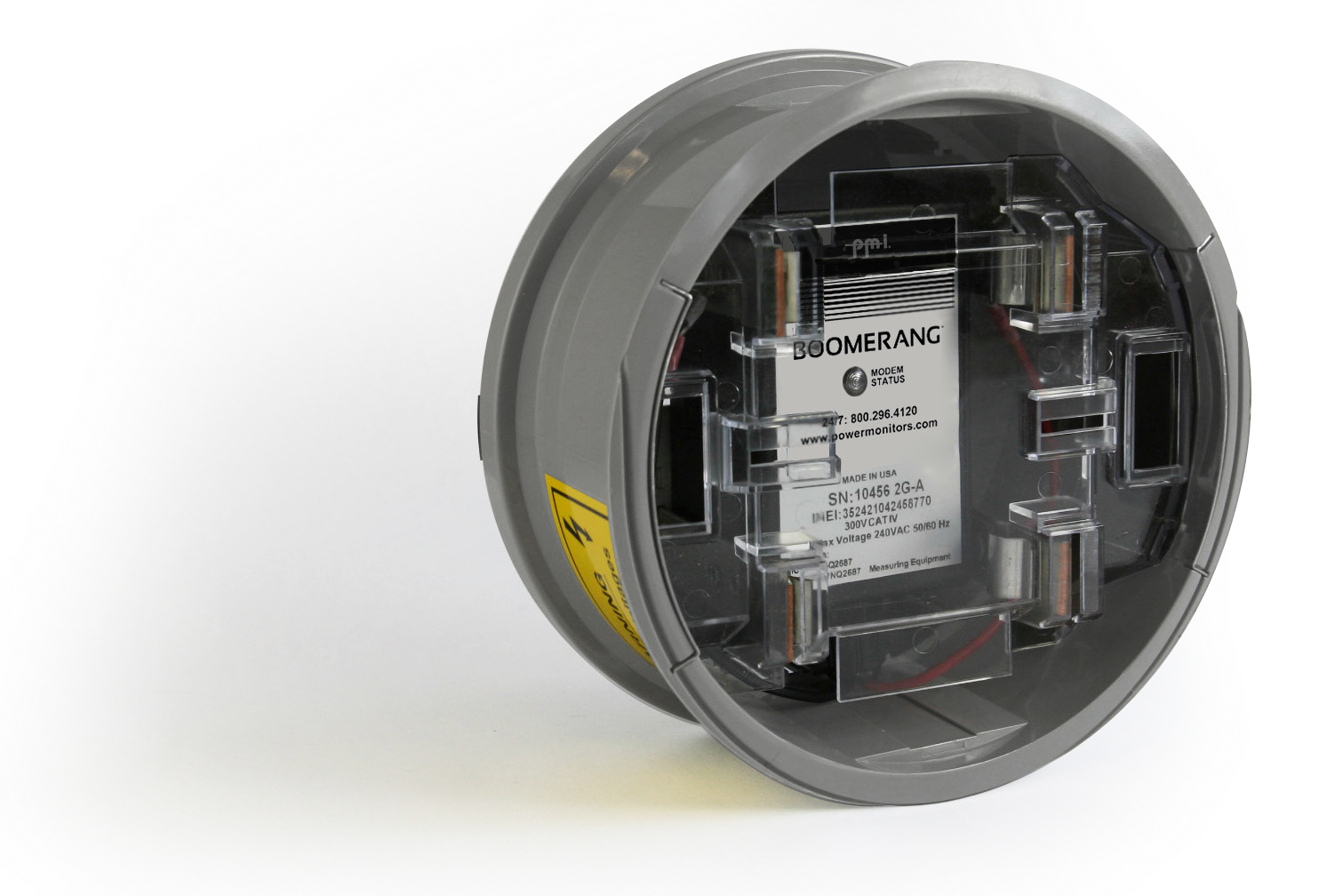
The Boomerang voltage monitor has been designed with the capability to be a DNP3 outstation for a SCADA system. As previously discussed, an outstation can collect various types of data for the SCADA system to utilize. It can also receive data from the master for settings such as thresholds, timing or scale factors. This data is arranged by object type and points within each type that details the specific pieces of data. The Boomerang supports six object types with various points available within each type:
- Type 1 (binary input): This type of data is a collection of various on/off or true/false conditions
- Type 2 (binary input change): This type indicates that a change has occurred in one or more of the type 1 binary inputs. Type 2 data is sent to the master station as events to notify it of a change in binary input states
- Type 20 (binary counter): This type of data contains integer counts of events and time durations tracked by the Boomerang.
- Type 30 (analog input): The type 30 data is a collection of numerical values representing various readings being collected by the Boomerang (voltages, cell tower information, frequency, static unit data, etc.).
- Type 32 (analog input change): Similar to type 2 data, type 32 data is sent to the master as events to indicate a change in one or more of the analog inputs.
- Type 40 (analog output): The type 40 data holds values that are used by the Boomerang to modify its behavior during voltage monitoring. These are values that can be changed by the master station if desired. Type 40 data has default values so that a master station is never required to send them.
The list of object types and data points supported by an outstation is called a point map. Each point can have a number of variations (as noted in Table 1) that describe the underlying size of the data element and the potential precision of the data value. The details of point variations is beyond the scope of this paper. The point map in Table 1 shows the data available from a Boomerang via the DNP3 protocol.
Table 1. Boomerang Point Map
| Point No. | Description |
|---|---|
| Object Type 1 – Binary Input (all variations) | |
| 0 | Voltage low-low alarm status indicates that the measured RMS voltage has fallen below the threshold set in object type 40 point 1 |
| 1 | Voltage low alarm status indicates that the measured RMS voltage has fallen below the threshold set in object type 40 point 2 |
| 2 | Voltage high alarm status indicates that the measured RMS voltage has risen above the threshold set in object type 40 point 3 |
| 3 | Voltage high-high alarm status indicates that the measured RMS voltage has risen above the threshold set in object type 40 point 4 |
| 4 | Voltage normal status is true when the measured RMS voltage is within the threshold boundaries of object type 40 points 2 and 3 |
| 5 | Battery low is true when the measured battery voltage has fallen below its recommended operating value |
| 6 | RSSI low indicates a cellular connection signal strength that has fallen below the threshold set in object type 40 point 7 |
| 7 | An internal error log entry has been generated |
| 8 | An internal warning log entry has been generated |
| 9 | An internal severe log entry has been generated |
| 10 | Cellular network connection has failed |
| 11 | Network data usage is deemed to be high for this device |
| Object Type 2 – Binary Input Change | |
| All object type 1 binary points can generate object type 2 events to the master | |
| Object Type 20 – Binary Counter (all variations) | |
| 0 | Number of times voltage low has been detected based on object type 1 point 1 |
| 1 | Number of times voltage low-low has been detected based on object type 1 point 0 |
| 2 | Number of times voltage high has been detected based on object type 1 point 2 |
| 3 | Number of times voltage high-high has been detected based on object type 1 point 3 |
| 4 | Cumulative number of seconds in the voltage low state |
| 5 | Cumulative number of seconds in the voltage low-low state |
| 6 | Cumulative number of seconds in the voltage high state |
| 7 | Cumulative number of seconds in the voltage high-high state |
| 8 | Cumulative number of seconds in the voltage normal state |
| 9 | Number of seconds in the low RSSI state |
| 10 | Total number of network errors detected |
| 11 | Total number of 8-bit data bytes sent over the network |
| 12 | Total number of 8-bit data bytes received over the network |
| 13 | Total number of TCP network errors detected |
| 14 | Total device up time in seconds |
| 15 | Total network up time in seconds |
| Object Type 30 – Analog Input (all variations) | |
| 0 | RMS voltage based on 1 second averaging |
| 1 | RMS voltage based on the averaging period specified in object type 40 point 0 |
| 2 | Frequency of the measured sine wave in Hertz |
| 3 | Battery voltage measurement |
| 4 | Detected cellular RSSI value |
| 5 | Cell tower ID number |
| 6 | Cell tower LAC (Location Area Code) |
| 7 | Firmware version of the Boomerang |
| 8 | Physical serial number of the Boomerang unit |
| Object Type 32 – Analog Input Change | |
| All object type 30 analog input points can generate object type 32 events to the master | |
| Object Type 40 – Analog Output (all variations) | |
| 0 | RMS voltage measurement averaging period in seconds (affects the value reported in object type 30 point 1) |
| 1 | Low-low RMS voltage threshold value |
| 2 | Low RMS voltage threshold value |
| 3 | High RMS voltage threshold value |
| 4 | High-high RMS voltage threshold value |
| 5 | Hysteresis (+/- volts) value used to smooth out measurements near the threshold boundary conditions |
| 6 | Delay time in seconds the measured RMS voltage must exceed a programmed threshold boundary before triggering an alarm |
| 7 | Cellular RSSI threshold value |
| 8 | Scaling factor to be applied to voltage measurements |
| 9 | Number decimal places of resolution desired in the voltage measurements |
Conclusion
The Boomerang Voltage Monitor has been designed for use with PMI’s Canvass web application but also as a DNP3 enabled outstation for general use with SCADA systems. The Boomerang(s) could be the only outstations in use on a SCADA network or they could be combined with any other types of outstations from other vendors due to the generic nature of the DNP3 protocol. This makes the Boomerang family of products a powerful and versatile tool to meet voltage monitoring needs.
The SCADA system master station must be configured to recognize the Boomerang as an outstation and it must be configured to collect the specific pieces of data from the point map that it will utilize. This could be one or many or all of the individual data points that are available in the Boomerang.