Abstract
This white paper walks the reader through a method to take basic core PQ measurements and derive several other measurements (such as 60Hz power, Voltage and Current THD, distortion power factor, voltage and current unbalance and even symmetrical components).
What Are These Core Measurements?
By recording voltage and current RMS stripcharts and voltage and current 1st harmonic (Fundamental) magnitudes and phase angles several other useful power quality measurements can be computed.
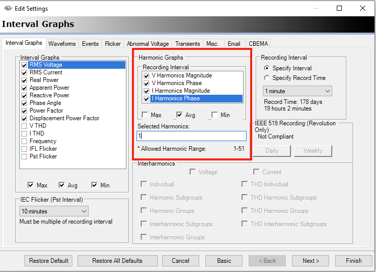
To record these measures, simply select the 1st harmonic magnitude and phase when initializing your recording.
For the purposes of this recording, we will record:
- RMS Voltage
- RMS Current
- Real Power
- 1st (Fundamental) Voltage Harmonic Magnitude
- 1st (Fundamental) Voltage Harmonic Phase Angle
- 1st (Fundamental) Current Harmonic Magnitude
- 1st (Fundamental) Current Harmonic Phase Angle
Mathematical Computations
This section is going to go through the mathematical computations for:
- Creating the 60Hz complex phasor from the 1st Harmonic (Fundamental) magnitudes and phase angles
- THD from the 60Hz phasor magnitude and the RMS for the same measure (ex. 60Hz Voltage Phasor and RMS Voltage)
- Symmetrical Components from the derived/reconstructed 60Hz Phasors
- Unbalance from the computed Symmetrical Components
- Apparent Power
- Displacement Power Factor
- Reactive Power
- Distortion Power Factor
To begin, recall from trigonometry the following equation to identify any point on the unit circle:
= R (cos (θ) + j sin (θ)) where is the position on the unit circle. This concept is extended to sine waves where the radius R becomes the amplitude of the wave and θ is the time-delay (or phase shift) of the waveform in, say, an AC electrical system.
With these two pieces of information (magnitude and phase), we can reconstruct the 60Hz phasor with the trigonometric function listed above.
Incidentally, recording the 60Hz magnitude and phase as a time series record with PMI’s recorders is pretty straightforward. The Eagle, Revolution, Guardian, Tensor, Seeker and Bolt platforms all allow the user to select individual harmonic magnitudes and phase angles up to the 51st. For the purposes of this paper, it is assumed that the reader has, at the very least, selected the 1st harmonic magnitude and phase angle as stripchart measurements. (See section above “What Are These Core Measurements” for instructions on recording these records.)
To construct the 60Hz phasor from the stripchart traces in a PMI PQ recording, simply take the following:
real = Fmag · cos (Fphase)
imag = Fmag · sin (Fphase)
First Stop: THD
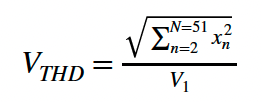
To compute Voltage (or Current) THD, the traditional method is to take an FFT of the waveform and then take the square root of the sum of the squares of the magnitudes of the 2nd through the 51st harmonic and divide them into the fundamental magnitude. (This is THD-F.)
However, the THD value can be reconstructed with just the 60Hz phasor and the RMS value for the measurement in question (voltage or current). (An important note here is that the RMS value ends up incorporating all of the harmonic content of the waveform, not just those to the 51st order. A higher sampling rate necessarily means that the THD computed in the following method will be slightly higher than those that limit their components to the 51st. In the case of PMI recorders, the default sampling rate is 256 samples per cycle, meaning that the 127th harmonic is the theoretical highest order harmonic at which energy can be measured.)
We begin by using the magnitude from when we composed our 60Hz phasor in the last section (the value that was recorded in the stripchart record).
We can compute the VTHD with the following simple formula:
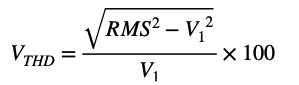
Note: V1 is the fundamental magnitude.
Next Stop: Symmetrical Components
A previous white paper was dedicated specifically to this task. It contains these same derivations and links to an Excel spreadsheet that the reader can use to compute symmetrical components by exporting values directly from ProVision. That spreadsheet can be found linked in this paper and can be modified to compute any of the measurements listed here.
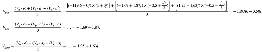
Mathematically, the positive, negative and zero sequence complex outputs can be computed with the following linear algebraic equation:
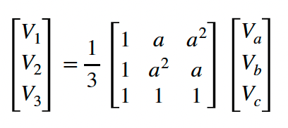
In this equation:
V1 is the Positive Sequence Voltage. Note that this is a complex number.
V2 is the Negative Sequence Voltage. This, too, is a complex number.
V3 is the Zero Sequence Voltage. As with the other two components, this is a complex number as well.
a is defined as
a² is defined as
a³ is defined as 1.
Va, Vb, and Vc: These are the channel 1, 2 and 3 voltages respectively. Note that these are the complex 60Hz phasors as well. The reader should use the complex phasors derived in the prior section.
Unbalance can be computed from these complex results by taking the negative magnitude divided by the positive magnitude:
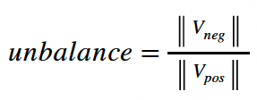
× 100%
Apparent Power
To compute Apparent Power, we can simply take the product of RMS Voltage and RMS Current. Note that these values were selected to be recorded in the first step when configuring the recorder.
Displacement Power Factor
Displacement Power Factor (DPF) is the angular displacement between the 60Hz Voltage and Current phasors. To compute this value, we simply subtract the Current Phase Angle from the Voltage Phase Angle (60Hz or Fundamental phase angles).
Next, we take the cosine of this angle to get the displacement power factor measurement itself.
dpf = cos (Vphase – Iphase)
Reactive Power
Reactive power can be computed by combining our apparent power measurements above with the displacement power factor measurements we just made.
Instead of using the actual displacement power factor, however, we will use the intermediate computation of the displaced angle.
If we take the product of the sin of this angle and the computed apparent power value, we will get reactive power.
ReactivePower = sin(θ) · VAR
where θ is the angular difference we computed between the 60Hz voltage and current phasors.
A Brief Note on Real Power
The reader may have noticed that in the opening to this paper, we recommended recording real power as its own independent measurement. This is because the proper computation of real power for a complex sine wave (that is, a sine wave that consists not only of the pure fundamental, but also multiple harmonics at varying magnitudes and phase angles) require the instantaneous product of the sine waves themselves. It is defined as the mean of the component-wise product of instantaneous voltage and current. Since those values are not available to us at this stage, we are not able to compute that value.
Final Stop: Distortion Power Factor
Finally, we can compute Distortion Power Factor (which is the measure of how much the THD of a load decreases the power delivery efficiency to the load). Mathematically, this is simply defined as the ratio of the fundamental magnitude over the RMS value. We’ve computed both of these already, so computing this is quite straightforward.
DistortionPowerFactor =
where I1 is the current fundamental harmonic magnitude.
Examples of Algebraic Computations for All Measurements
For the purposes of these computations, the following values will be used:
- Va RMS (VRMS) = 120.2
- Va Fundamental Mag (||V1||) = 119.6
- Va Fundamental Phase (∠V1) = -180 Degrees
- Ia RMS (IRMS) = 127.0
- Ia Fundamental Mag (||I1||) = 171.0
- Ia Fundamental Phase (∠I1) = 173 Degrees
To convert an angle from degrees to radians, simply multiply the angle by .
We must first compute the complex phasors for both V1 and I1. This is defined as:
||V1|| · cos (∠V1) + j||V1|| · sin(∠V1)
Substituting our values, we get:
119.6 · cos (-180) + j119.6 · sin (-180) = 119.6 · -1 + j119.6 · 0 = -119.6 + 0j
Our Voltage A-phase Phasor is now -119.6 + 0j
Working through the same formula to compute the 60Hz current phasor, we get:
171 · cos (173) + j171 · sin(173) = -169.725 + j20.840
Our Voltage A-phase Phasor is now -119.6 + 0j
Our Current A-phase Phasor is now -169.725 + 20.840j
All three phases of voltage and current RMS, magnitudes, phases and complex phasors can be seen in the table below:
| RMS | Fund. Mag | Fund. Phase | Cpx. Phasor | |
|---|---|---|---|---|
| Va | 120.2 | 119.6 | -180 | -119.6+0j |
| Vb | 120.6 | 119.8 | 61 | 58.08+104.78j |
| Vc | 121.1 | 120.5 | -56 | 67.38-99.90j |
| Ia | 172.0 | 171.0 | 173 | -169.73+20.84j |
| Ib | 119.0 | 118.0 | 80 | 20.48-116.21j |
| Ic | 122.0 | 120.0 | -74 | 33.08-115.35j |
We will use these values for symmetrical component computations later. First up is computing THD.

For Apparent Power, all we need is the product of the RMS Voltage and the RMS Current:
ApparentPower = VRMS × IRMS = 120.2 × 172.0 = 20.6744 kVA
Reactive power can now easily be derived:
ReactivePower = ApparentPower x sin (Δθ) = 20.6744 x sin (-180 – 173) =-0.909 2.52kV AR
Using the Δθ that we computed in the last measurement (reactive power), we can now compute Displacement Power Factor:
DPF = cos(-180 – 173) = cos(-353) = 0.9925
To compute distortion power factor, we simply use the formula from above:
DistortionPowerFactor = = = 0.9942
We will begin by (re-)defining the following values:
- a =
- a² =
- o = 1 + 0j
Finally, let’s work through some examples of computing symmetrical components using the complex phasors we computed above in the first step in this section.
Substituting the current phasors for the voltage phasors will allow the reader to compute the positive, negative and zero sequence symmetrical components for current.
The next step in our process is to compute the magnitudes for each of the sequence components that were just computed. It’s the standard magnitude calculation:
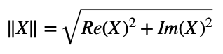
Therefore, our magnitudes are as follows:
Vpos = 119.9
Vneg = 2.5
V0 = 2.5
And finally, unbalance can be computed as the quotient of negative over positive sequence magnitudes:
X 100% = Vunbal = 2.10%
All of the current equivalents (positive, negative and zero sequences, unbalance and magnitudes) can be computed by using the complex current phasors instead of the complex voltage phasors in these equations.
Conclusion
This paper has demonstrated that by recording a couple of key measurements (namely the RMS and fundamental harmonic magnitudes and phase angles), several useful power quality metrics can easily be computed on-the-fly.
