Abstract
TLARs are PMI’s iron core CT (Current Transformer) clamps, available in various probe and channel configurations. These clamps are used for lower range current measurements, with ranges of 20A or 200A. Most of PMI’s recorders offer the ability to measure current via user selectable Flexible CTs or iron core TLAR clamps. This white paper explains how current transformers work generally and how PMI TLAR CT work specifically, and tips for TLAR use.
Basics of a Current Transformer
A current transformer has two sets of windings, primary and secondary, around a magnetic core. See Figure 1. The primary conductor usually has one winding through the center of the core and the secondary conductor typically has many windings. When alternating current flows in the primary circuit a proportional current flows in the secondary circuit. This property is caused by the magnetic field induced by the primary coil. This field creates magnetic flux inside the iron core material, which then induces a voltage in the secondary winding. If the secondary winding is shorted, or connected with a resistor whose resistance is low, the induced voltage produces a current flow which is proportional to the primary current.
The current on the secondary circuit (IS) is expressed as a formula of the windings on the primary circuit (NP, usually 1) divided by the windings on the secondary circuit (NS) times the current (IP) on the primary circuit.
Or in the usual case of one primary winding:
Often current transformers have their currents expressed as a ratio such as 200:5. This means that if 200 amps are flowing on the primary then 5 amps are flowing on the secondary. The maximum rated current is specified with this notation (in this case, 200 amps on the primary, and equivalently, 5 amps on the secondary). In reality a 200:5 CT is a 40:1 ratio, with one primary turn and 40 secondary turns, but the 200:5 notation conveys the nominal max current as well as the ratio. A secondary of 5 amps is very common in the utility industry for use in metering. The TLAR clamps are perfect for the 5 amp secondary current of metering CTs.
Basics of PMI TLAR CTs
PMI TLAR CTs are iron core current transformer clamps. The clamps, when the jaws are closed, form the magnetic core and the wire inside the clamp is wound around this core to produce the secondary winding. The conductor that the TLAR is clamped around forms the primary winding. See Figure 2.
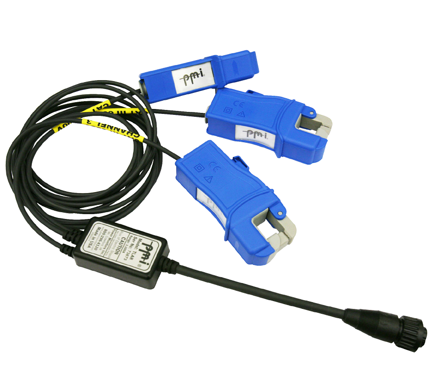
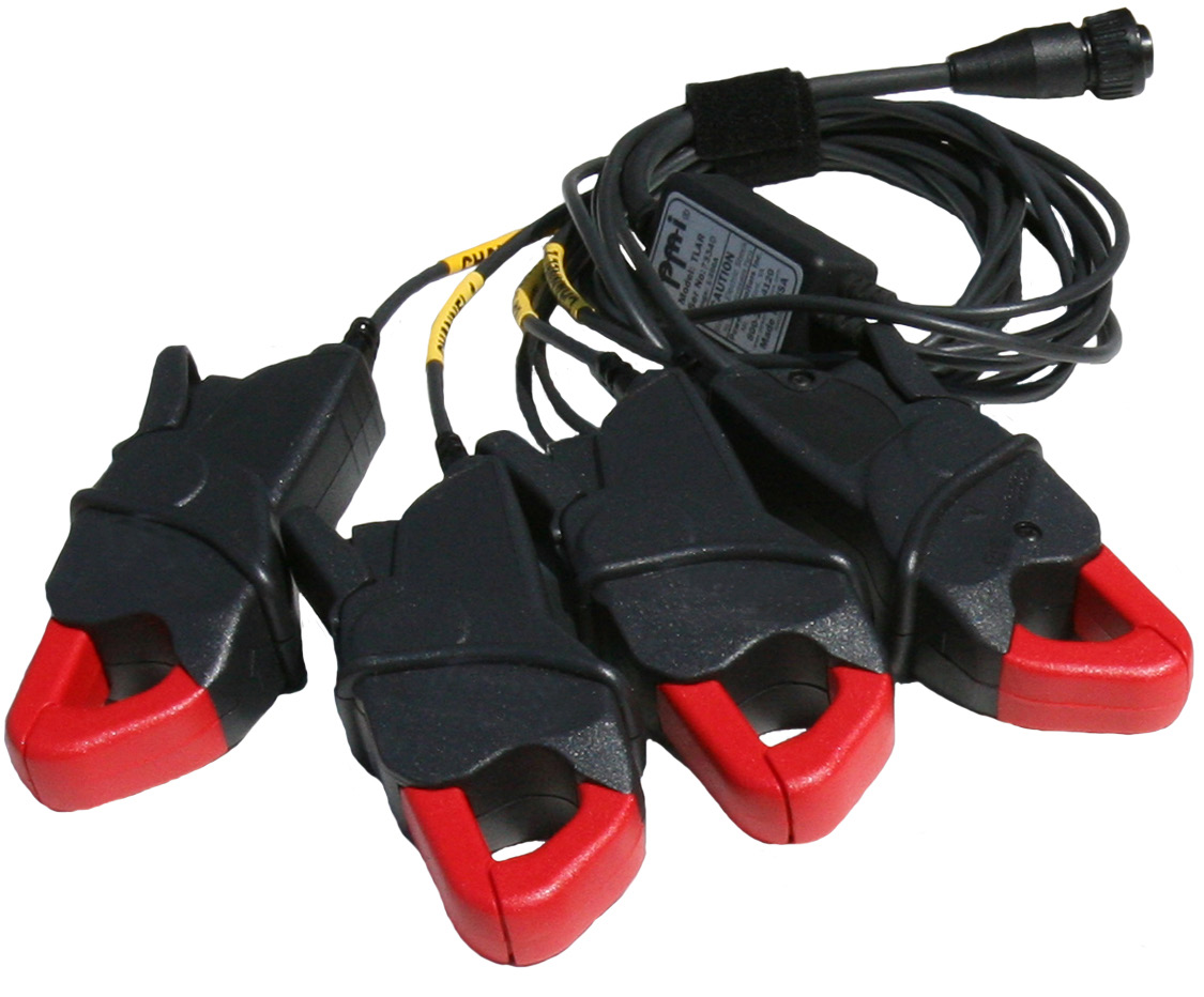
TLARs are available in two styles (Figure 3) with one being larger than the other and with two, three or four channels. The larger one (Figure 3) will fit a 4/0 AWG aluminum direct burial cable, the smaller one (Figure 4) fits in small spaces better.
The TLAR clamps are used for lower range current measurements, with adjustable gain of 20A or 200A full scale. They are well suited for low current measuring when set on the user adjustable 20A range, designed for secondary monitoring on 5A metering CTs.
Current clamps and recorders can have different number of channels. If there are more channels in the clamp than in the recorder, the additional channels are ignored. If the recorder has more channels than the clamps the missing channels will be read as zero.
A traditional simple current transformer can produce a dangerous overvoltage on the secondary winding in some situations. The CT will attempt to develop whatever voltage is required to force the needed secondary current (in proportion to the primary). If the secondary coil is open circuited, in theory infinite voltage is required. The physics of a real CT can result in several hundred volts with an open secondary coil, and can be a shock hazard. All PMI CTs are protected against dangerous overvoltages, with a combination of suppression devices, and internal resistors.
The TLARs connect to 3-phase Boomerangs, Eagles, Revolutions, ViPs, and 600P recorders.
Tips for Using TLARs
Each TLAR clamp has an arrow to indicate the direction of current flow. Always make sure that the directional arrow on each clamp is pointing towards the load. If reversed then the current signal will be 180 degrees out of phase. Use a -1 scale factor in ProVision or Canvass to help if analyzing recordings with reversed clamps. See the white papers on scale factors in ProVision and Canvass for more information about scale factors.
Make sure that the clamp is fully closed. Any slight gap creates inaccuracies. A slight gap can cause the TLAR clamps to buzz. If you hear buzzing make sure that the clamps are fully closed. Debris on the clamps can cause gaps. It is recommended that the clamps be inspected and cleaned as needed before use. Any gap in the clamp jaws prevents the magnetic circuit in the core from being completed, and can cause clamp overheating as well as inaccurate measurements.
Do not place the body of the clamp against high current conductors. If the clamps are close enough to conductors carrying large loads they can magnetically couple and cause inaccurate readings.
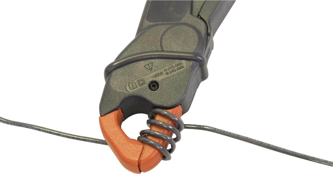
The primary can be wrapped multiple turns around the clamp for increased resolution at very low currents. If the primary is wrapped, then adjust scale factors in ProVision or Canvass based on the number of times the primary is wrapped. In some cases, a 5 amp nominal metering CT output may be well under 5 amps most of the time. If the monitored current is much under 1 amp on average, wrapping multiple turns of the metering CT secondary around the clamp will help improve the resolution.
TLARs are used for lower range current measurements, most commonly used on 5A CT secondaries, light commercial and residential locations, or for monitoring single loads. Low current monitoring is very common in electrical systems when the load is very small or the current is stepped down by metering CTs to the 5A secondaries. In this case the TLAR can be set to the 20A current range setting to obtain the best recording resolution. It is important to select the optimal range with ProVision or Canvass.
The TLARs can be damaged by sustained overcurrent as this can cause overheating.
Comparison of PMI TLARs to PMI Flex CTs
TLARs have several advantages over the PMI Flex CTs. One is better low current accuracy. The TLARs with their 20A range are better suited to measure the 5A secondaries. TLARs are also inherently less sensitive to conductor positioning than Rogowski coil sensors.
There are a few disadvantages of iron core clamp CTs compared to the Flex CTs. The rigid construction can make it more difficult to fit in tight enclosures. Another disadvantage is that sustained severe overcurrent can cause damage to the clamps because of overheating.
Conclusion
- TLAR CTs are current transformer iron core clamps for accurately measuring current especially at the low current ranges. They are usually the best choice for 5A secondaries.
- TLARs are available in two styles and in 2, 3 or 4 channel models.
- It is important to have the arrow on each clamp pointing towards the load.
- The primary can be wrapped multiple times around the clamp to increase resolution at low currents (as shown in Figure 5). This is especially helpful with very low metering CT outputs (under 1 amp). Just make sure to adjust the scale factors in ProVision or Canvass.
