Introduction
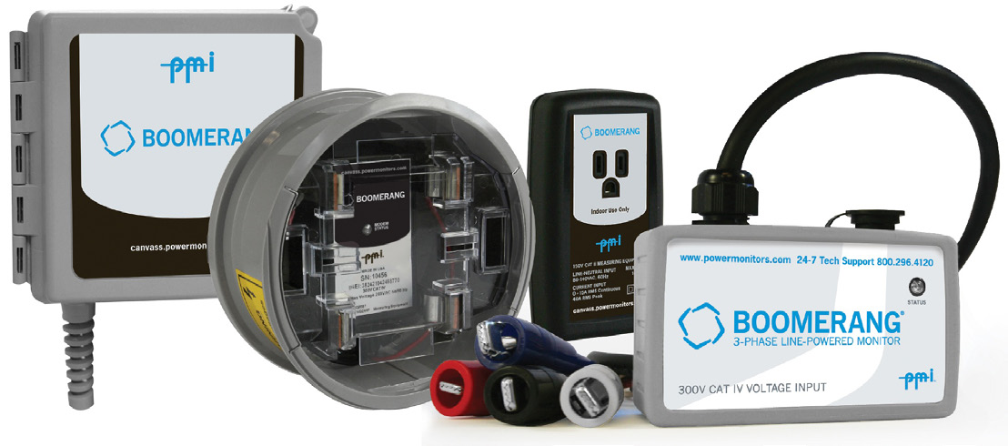
In addition to PMI’s cloud-based Canvass system compatibility, Boomerang distribution monitors including a DNP3 port for use in SCADA. Advanced distribution programs such as volt/VAR optimization, DER management, and outage notification require the Boomerangs to operate with SCADA automation controllers. One popular controller is the SEL RTAC line. Here an introduction to the RTAC is presented, along with a brief review of the DNP3 protocol, how to integrate a Boomerang with an RTAC, and a few examples of RTAC automation with the Boomerang. Additional information about the DNP3 point map for Boomerangs can be found in WP316 (DNP3 Point Map 2.0 Update).
What Is a Real Time Automation Controller?
A Real Time Automation Controller (RTAC) is a hardware device manufactured by SEL that collects data from DNP outstations, provides protocol conversion, and provides an engine for advanced automation support to act on received data. RTACs are available in several form factors but mostly provide the same functionality. An RTAC may be used to collect data from multiple types of outstations using various protocols including DNP3, SEL protocol, modbus, IEC 61850 GOOSE and more. After receiving the data, the RTAC can map the data to other data types for use by different protocols. Additionally, the RTAC can be programmed with custom logic to send outputs to relays and other control hardware, or upstream alerts, based on received data.
What Is DNP3?
DNP3 is a protocol that is widely used by SCADA systems to monitor and control a wide range of devices. DNP3 is used to read data from predefined points in separate groups on an outstation, or send control data to points in the same manner. Group types are defined by the protocol (such as a binary output for a relay, or an analog input for a voltage reading), while the individual point map is determined by the manufacturer of the outstation. Generally, the DNP3 master polls all outstations on a periodic basis. DNP3 also supports unsolicited events, where an outstation sends the master an alert or update based on programmable triggers. Unsolicited report by exception is a key aspect of the DNP3 protocol that makes advanced automation schemes possible without excessive network traffic from constant polling. Boomerangs use unsolicited events to send analog and binary inputs when voltage, current, or power readings cross configurable thresholds.
Advantages of a DNP3 Concentrator
A DNP3 concentrator can be useful when polling a large number of outstations. Using an RTAC to poll hundreds of devices, using various protocols, and mapping those to DNP3 for use by an upstream SCADA master can reduce the load on the master itself. The SCADA master only needs to poll one DNP3 point map, which contains aggregated data from the devices that the RTAC itself polls. Additionally, the protocol conversion of an RTAC allows the SCADA master to receive data from outstations using protocols that the master itself does not support directly. The RTAC also supports unsolicited events from DNP3 devices. In a typical configuration, field devices report via exception to an RTAC (through cell or other remote communications), while the RTAC itself is polled by an upstream master through an Ethernet or fiber connection. This relieves the unsolicited requirement burden on upstream master and provides a common point map to the master.
Configuring a Boomerang in an RTAC as a DNP3 Slave
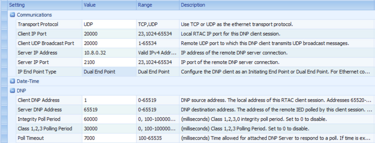
Since Boomerangs implement the DNP3 protocol, adding a Boomerang as a DNP3 slave in an RTAC is straightforward. A device template has been created that can be imported; it includes all the relevant DNP3 points and most of the required configuration for the RTAC. Further configuration required for each device includes: Server IP Address, Server IP Port, and Server DNP Address. The Server IP Address should be the IP address of the Boomerang, and the Server IP Port should be configured to the DNP3 port of the Boomerang (default 2100). The Server DNP Address should be configured to the Boomerang’s DNP Address (default 65519). Since a DNP3 channel is established for each separate IP address, the Server DNP Address can be the same for each Boomerang. The Client IP Port must be unique for each device.
If the use case is receiving unsolicited events from a Boomerang, a longer poll time can be configured to save bandwidth and resources on an RTAC (as shown in Figure 2).
Utilizing Unsolicited Events
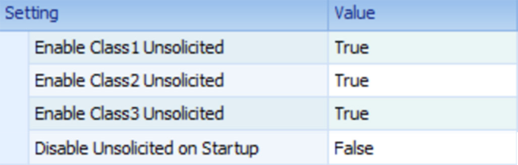
If not using the provided device template, the settings related to unsolicited events will need to be configured using the “Advanced Settings” checkbox. By default, the RTAC will send a message to DNP3 slaves telling them to disable unsolicited events and, the RTAC will not accept unsolicited events from slaves (as shown in Figure 3).
Boomerangs can be configured with thresholds to send unsolicited events. These unsolicited events are triggered based on the programmable window averaged DNP point. For example, a Boomerang will send an unsolicited event to Analog Input 101 if the windowed average voltage on channel 1 crosses any configured threshold for channel 1 voltage, and will send an unsolicited event to Analog Input point 306 if the windowed average current on channel 3 crosses any configured threshold for channel 3 current. The averaging window can be set as short as 1 second, or as long as 15 minutes.
Configuring DNP3 Event Thresholds
Event thresholds for Boomerangs are configured via DNP3 Analog Outputs on the Boomerangs. As detailed in WP316, these threshold values can be written to, and then writing 12345 to analog output 20 will commit the thresholds to flash storage, so that they persist through device reboots. The threshold hold off will cause the Boomerang to delay triggering the unsolicited events. If the event is resolved within the hold off period, an event is not triggered. The threshold hysteresis will smooth out “chatter” when the voltage is hovering around a threshold. Finally, the averaging window will smooth out any sudden voltage sags or swells by computing a running average of the value over the windowed time period.
For example, writing a value of 550 to analog output point 100 will set the “Voltage low threshold” to 55.0 volts on channel 1. Then, writing a value of 12345 to analog output point 20 will save the set values to permanent memory.
Using the Tag Processor
The SEL RTAC’s Tag Processor is where all of the SCADA data conversion and concentration takes place. The Tag Processor allows the mapping of tags to other tags and allows structured text programming to act on the values of the tags.
Figure 4 is an example using structured text to turn on the first integrated LED of the RTAC when the voltage on channel 1 drops below 55 volts, and turn it off when it’s above 55 volts.
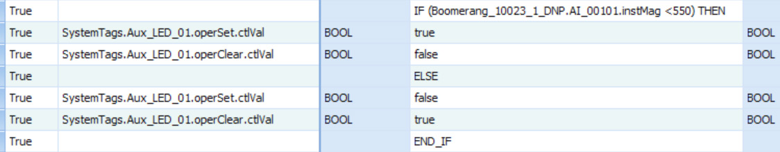
Figure 5 is an example of mapping tags from multiple Boomerangs to a single DNP Server Shared Map.

Using the RTAC as a DNP3 Slave for an Upstream DNP3 Master
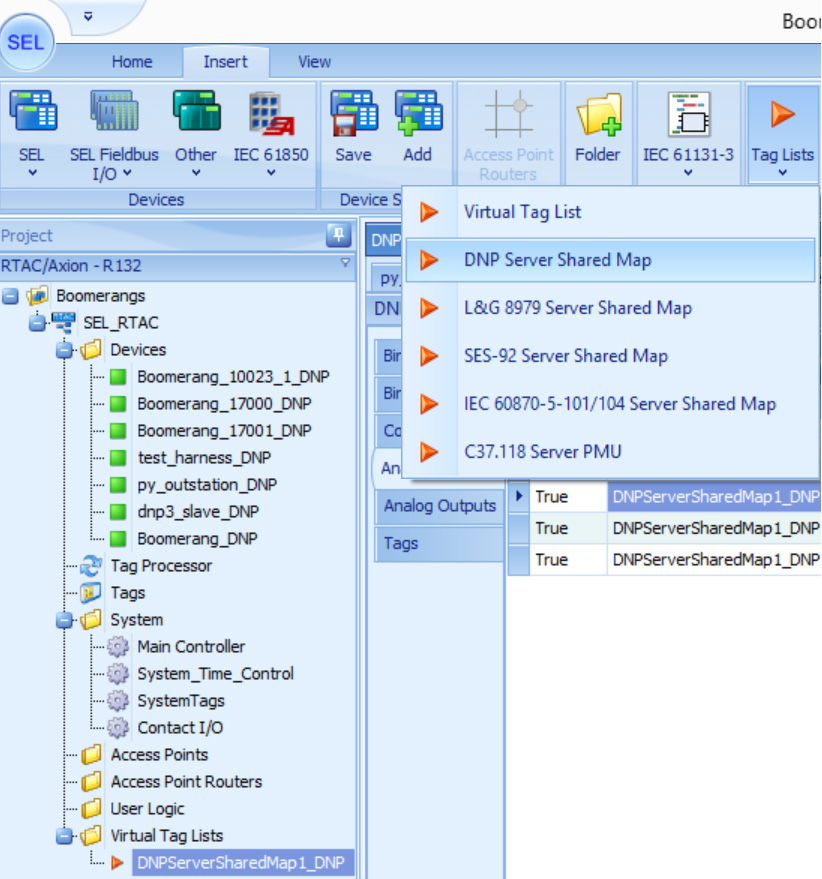
Now that Boomerangs are being polled individually by the RTAC, they can be mapped to a DNP Server Shared Map. The values in this map will be polled by the upstream DNP3 master for DNP3 concentration. On the insert tab, create a new DNP Server Shared Map from the Tag Lists dropdown (as shown in Figure 6).
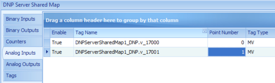
Then, create some analog inputs in the shared map. The ones below have been suffixed with the measure and serial number of the Boomerang, but the name is not important (as shown in Figure 7).
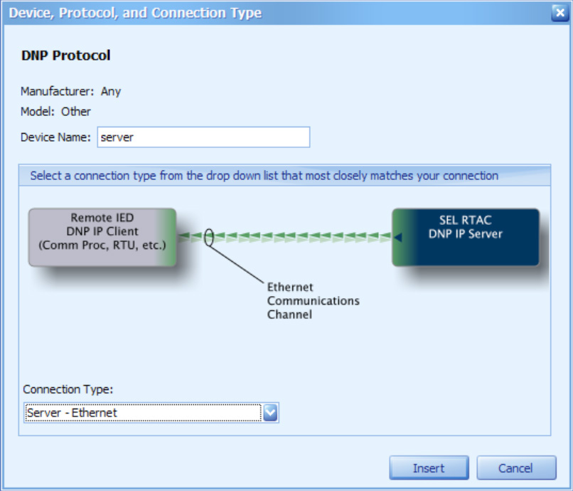
Then, create a new “Other” device, with the DNP protocol, and the “Server – Ethernet” connection type. This is the device that the upstream DNP3 master will poll (as shown in Figure 8).
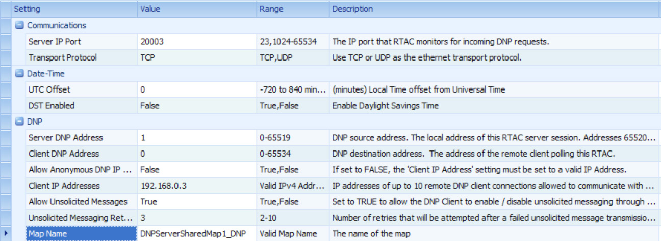
Finally, configure the device settings to be compatible with the upstream DNP3 master. The most important configuration detail is the Map Name, in which the DNP Server Shared Map should be selected from the dropdown (as shown in Figure 9).
Conclusion
Utilizing PMI Boomerangs and an SEL Real Time Automation Controller, it is possible to collect data via the DNP3 protocol, manipulate incoming data in real time, concentrate and process that data, and send it to an upstream DNP3 master. This reduces complexity and resource usage of a SCADA master or outage management system. Additionally, collecting the data via unsolicited events and longer poll periods reduces bandwidth usage to cell-networked devices.
