Abstract
Stripchart recording is an important tool for analyzing complex data. It provides a visual means to easily digest extensive quantities of recorded information over long time periods. In most cases, the stripchart logging interval is relatively slow (e.g. 1 minute, or 5 minutes), to allow the coverage of many days or weeks. Min, max, and average point logging at the slow interval rate provides one-cycle worst-case values, which is usually sufficient for most PQ issues such as voltage sags. An exception to this usage is cycle stripchart recording. With a cycle interval, data accumulation is much faster, but the time resolution is much higher. The use of the cycle interval is described here.
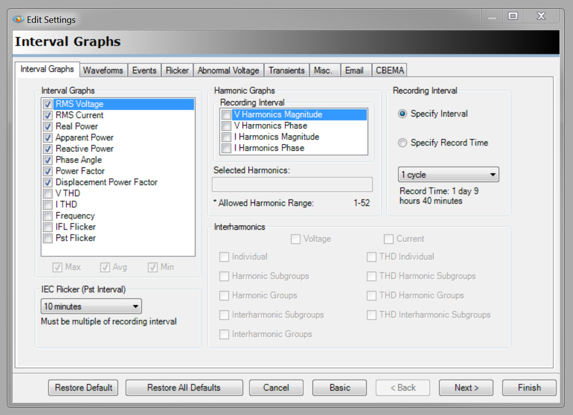
Stripchart recording setup in ProVision is shown in Figure 1. To initialize a recording device, left-click the device name under the Devices panel and click the advanced option to bring you to the dialog box in Figure 1. From here you can select the desired measurements. Keep in mind that any selected measurement type applies to all enabled channels. Enabling more measurements directly impacts the recording duration. To allow cycle stripchart viewing in ProVision, the recording interval must be setup for cycle capture. Click the Specify Interval radial button and select “1 Cycle” from the drop-down menu.
Overview of Cycle Stripcharts
Cycle stripcharts differ from traditional interval recordings in several ways. Single cycle recordings do not support the bottom five graphing types (Voltage THD, Current THD, Frequency, IFL Flicker, and Pst Flicker), as these measurements span across multiple cycles. Minimum and maximum values are also not applicable; data is only populated within the average field.
At first glance, you may think there is a significant difference between “1 cycle” interval recordings and traditional one second or greater interval recordings. However, “1 cycle” interval is simply the highest granularity for these power measurements. In fact, if minimum and maximum values were still logged, they would be identical to the average measurement. For example: given a one second interval, the recorder sums the measurement values of 60 cycles. It then divides the summation by 60 to provide the average value. During this time, it also keeps track of the highest and lowest measurement values within the dataset to populate the min and max data field. Now under the same methodology, if the pool size was limited to one cycle, we see how the min, max, average datasets would be identical. In lieu, we are given a significantly higher resolution recording. As expected, this consumes memory much faster due to the high storage rate.
Applications
Cycle level recordings generally become useful in situations where rapid changes are expected and one second averages are too coarse. In general, any voltage, current, or power fluctuation that occurs on a smaller time scale than the configured stripchart interval will be contained in a single min/ave/max set of values. While this is sufficient for many routine applications, and helps greatly with data reduction a long recording, more detail may be needed in specific cases. Some examples include: motor starts, generator switching tests, and detailed voltage sag analysis.
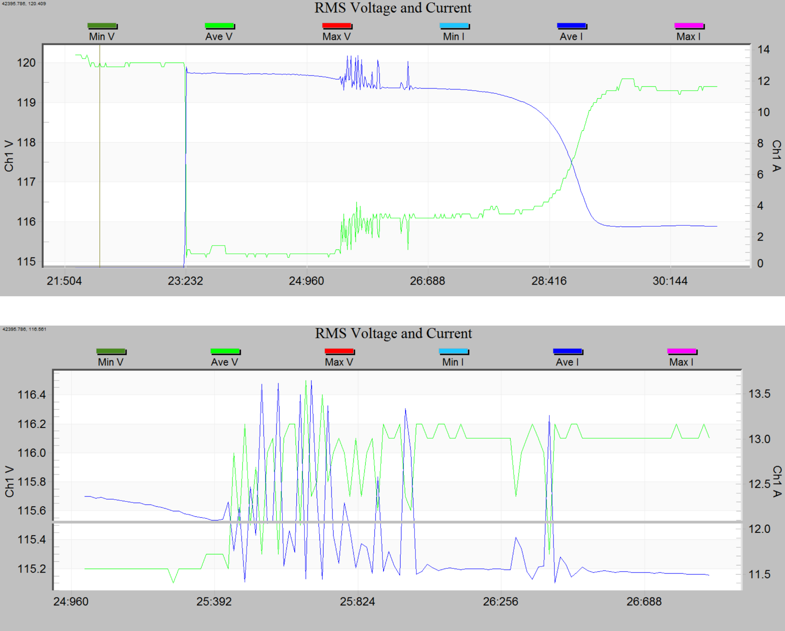
Figure 2 presents RMS voltage and current measurements from a single phase motor startup sequence taken from a PMI recorder. The device was initialized to “1 Cycle” interval recording to capture fine detail during the event. As you can see, a flutter is exhibited at the 25 second mark, lasting no longer than a second and a half. At the bottom of the figure, we see an expanded view revealing the fine detail. Had the recorder been set to the next larger interval (1 second), the spikes would have been combined together showing only a small blip in the recording.
In specific applications such as motor starts, generator or photovoltaic transfers, breaker operation, etc. where the specific equipment being monitored may be operated at will, the cycle interval provides the highest stripchart resolution. These recordings are usually short – the recorder is initialized, the equipment is operated, and then the data immediately downloaded and analyzed. Cycle interval recording is ideal for greater time resolution instead of a long recording time.
Alternatives to Cycle Stripcharts
Cycle stripcharts offer the finest level of logging detail before moving into raw waveform captures. Unfortunately, this resolution requires a large memory footprint. If the monitored system nominally operates at steady-state conditions, the bulk of the captured data would be uninteresting, and only a small chunk could be considered useful.
In some cases it is not appropriate to simply increase the interval time period. Recorders may need to be setup for long durations to capture an elusive event. While increasing the interval period would allow for long recording times, the important event may go undetected. In this situation, extensive detail is desirable during times of interest, and lower detail when not.
Event triggered waveform captures achieve a favorable balance. This topic is thoroughly covered in the white paper “Waveshape Triggering for Waveform Capture.” It lets the recorder be initialized with a coarse interval, while still capturing sharp moments of interest.
There is a downside to relying on waveform captures. While certainly an insightful means to evaluate a system, they consume costly amounts of storage space. Waveform captures are best used for events that last a few cycles, or tens of cycles. An event lasting many seconds long (hundreds of cycles) may easily fill up the recorder’s available space for waveform data. In many cases this fine level of detail is undoubtedly unnecessary.
Take Figure 3, this recording was taken from the same motor startup event and initialized to capture 256 samples per cycle. In the top plot the waveforms completely saturate the viewing field with cycles. While this certainly looks interesting, it is not very insightful for the amount of data it required to generate. However, if we generate an RMS plot from the recorded waveforms we can glean a much better understanding. (This is generated by clicking Graph → Waveform Capture → RMS Capture)
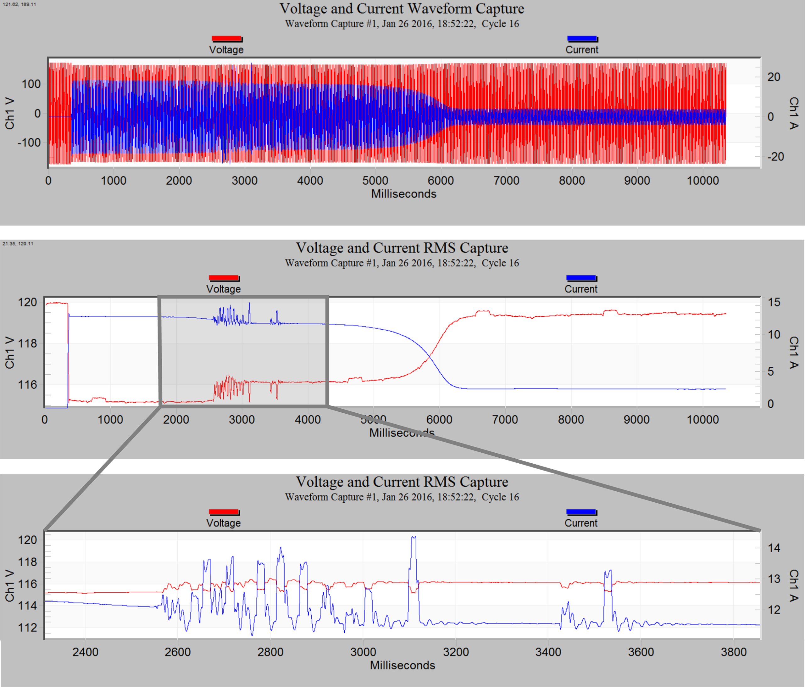
If we compare the zoomed in view of the shimmy event that occurred during the motor startup measurement, we see how much more detail is present in comparison to the plot in Figure 3. This is attributed to the RMS calculation performed on a 256 sample wide, moving window, effectively achieving a 65 microsecond interval RMS reading. In this case, there isn’t much more information gained otherwise shown in the previous recording setup with single cycle recordings. However, if a situation calls for the very finest resolution, this may be the appropriate use.
Conclusion
Single cycle interval recordings offer an effective resolution for inspecting voltage sags, generator switching tests, and motor starts or any event where one second averages are too coarse. “1 Cycle” interval recording is an extremely useful tool added to the arsenal of power quality analysis.
