Abstract
Measuring the current of residential, commercial or industrial applications is vital to get a complete power quality picture. This white paper covers various topics to effectively utilize the different types of current clamps available.
Clamp Types
Two different types of current clamps are currently available and some older types may still be encountered. These older types are still usable and fully supported by PMI recorders (where applicable).
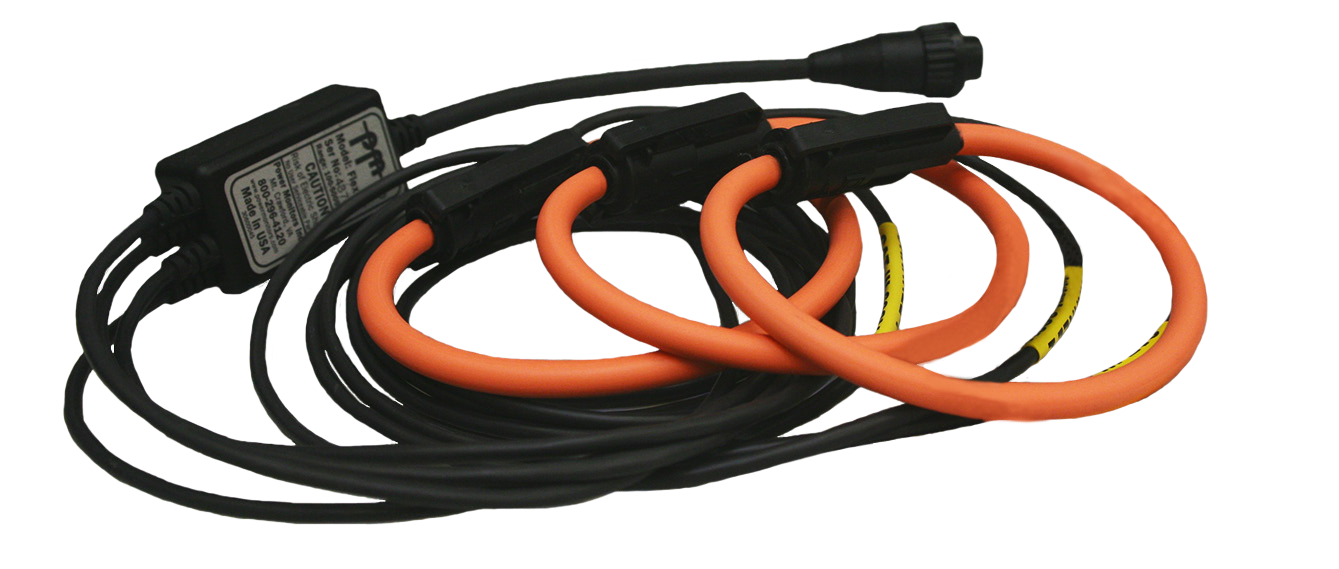
Flex CTs (shown in Figure 1) are available in various channel and length configurations to meet a wide variety of applications. These clamps are suitable for current measurement up to 5000A. The flexible current probes along with user adjustable range settings allow the recording resolution to be fine-tuned for better data analysis. The three ranges, 100A, 1000A, and 5000A, are designed for measuring actual load current for a single large load, an entire branch circuit, or a building service.
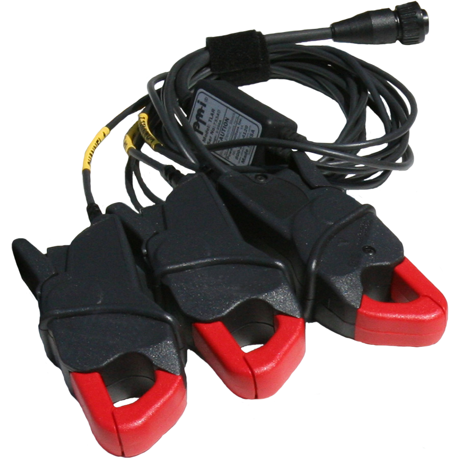
TLARs (shown in Figure 2) are available in various channel and probe configurations. These clamps are used for lower range current measurements, with ranges of 20A or 200A. They are well suited for low current measuring when set on the user adjustable 20A range, designed for secondary monitoring on 5A metering CTs.
Fixed range TLAR clamps are older types that do not have an adjustable range but were able to support multiple channels.
The oldest PMI clamps are single-channel iron core style, with a fixed range, and are not compatible with modern PMI recorders. Each clamp had a separate input on the recorder.
General Clamp Usage
It is important to use the right clamps for the job and the physical aspect of connecting (and sometimes disconnecting) clamps needs to be examined. The correct connection of the clamps is needed to get valid data readings and the method of connection will affect the data resolution.
The right clamp for the job begins with the anticipated range of current to be encountered. Residential and light commercial applications would utilize the lower range TLAR type of clamps while heavy commercial and industrial applications would likely use the higher range Flex CT type. Another consideration when choosing clamp type and programmable range is that the smaller ranges give better resolution for current and power measurement while the larger ranges are needed for heavy loads and current spikes.
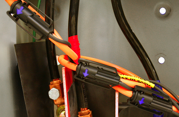
Regardless of clamp type, each has an arrow on the probe to indicate the direction of current flow (Figure 3). This arrow must always be pointing toward the load on the circuit when the clamp is attached. Clamps should always be attached or changed before recording begins to avoid erroneous data or gaps in the recorded data. Current clamps come in multi-channel configurations and may have a different number of channels than the recorder in use. This is not a problem since any additional channels are ignored by the recorder and any missing channels will be read as zero.
A technique mentioned in other white papers that bears repeating here is the method of wrapping a conductor one or more times around a current probe in order to increase the resolution of a reading. This technique, shown in Figure 4, actually lowers the effective full scale value by increasing the size of the sensed current, and then applying a user specified scale factor based on the number of times the conductor was wrapped. Although the full scale is lower, the resolution is improved. This is very commonly used when measuring small amperage with TLAR clamps. For example, a metering CT with an output of 0.2A full scale would be too low for even the 20A TLAR range, but wrapping 10 turns around the TLAR would boost that to the equivalent of 2A, which improves the resolution by 10X.
Flex CT Clamps
As the name implies, these clamps have a flexible probe used to encircle the conductor in order to measure current flow. Flex CTs are good for large commercial or industrial loads when measuring actual line current (as opposed to the secondary of a metering CT). The physically longer 36 or 48 inch CTs are useful when needing to clamp around several parallel conductors. When setting up these clamps for use it is important that the current carrying conductor being measured is situated away from the Flex CT connector. Ideally the conductor should be centered in the loop, but since this is usually not possible inside a crowded panel or transformer, having the conductor physically separated from the connector by at least 1 inch is recommended for maximum accuracy. Other current carrying conductors not being measured should also be kept away from the Flex CT connector. The connector is the point where the clamp loop can be separated (thus deviating from an ideal Rogowski coil), so this is the most sensitive area in regards to noise or inaccuracies being introduced into the measurement.
Flex CTs have a 5000A maximum range but this does not mean that they can only operate at this scale. In fact, the ranges supported are 100A/200A, 1000A and 5000A. These ranges are programmable via software or front panel selection depending on the recorder in use. The 5000A maximum denotes the maximum measurement range, not a physical limit since Flex CTs cannot be damaged by overcurrent.
Flex CTs are attached by encircling a conductor and sometimes with the conductor wrapped around the flexible cable of the probe. While this contributes to the ease of installation, it can also lead to unintended clamp damage if improperly installed or carelessly removed. The flexible cable has a 1 inch minimum bend radius to avoid cable damage. This bend radius should not be exceeded during installation. In addition, the probes should never be disconnected then simply pulled free since this may damage the connectors if they were to snag on a projection. Disconnect the probe and carefully unwrap it from the conductor that was being measured. Especially avoid pulling on the Flex CT to unlatch the loop connector.
TLAR Clamps
TLARs (True Low Amp Range) are iron core clamps. TLARs are good for residential or light commercial applications and are also suitable for monitoring a single industrial load. Iron core clamps are generally less sensitive than Rogowski-based probes to the position of the clamp on the conductor being measured. However they can be sensitive to nearby large current carrying conductors if they’re physically large and close enough to magnetically couple to the iron core, so care should be taken to avoid close proximity or contact with a bus bar or similar conductors. The clamp itself has two facing contacts when opened that must be free of dirt and debris. This will ensure a good magnetic connection of the two clamp halves when the clamp is closed which is necessary for maximum accuracy. If the CT is buzzing or humming, it’s likely not clamped completely.
TLARs have a programmable range of 20A or 200A full scale. The 20A range is suitable for measuring the secondary of a metering CT (often stepped down to a 5A nominal level) or for measuring an individual branch circuit with a 15 or 20A breaker. The 200A range would be used for heavier residential or light commercial as noted above. TLARs can be physically damaged by severe overcurrent (many hundreds of sustained amps) due to overheating regardless of the programmed range.
Selecting a Range
Selecting the correct range is as important as selecting the correct CT for a recording. Generally it’s best to use the lowest current range that will cover the highest expected current. For loads with high current spikes, such as motors, a range that’s 4-8X higher than the nominal load may be required to accurately measure inrush and other short-term current spikes. For example, a motor with a 50A running current may have a starting current over 300A, requiring a 1000A range (and Flex CTs) for accurately measuring the peak current. If the peak current isn’t as important for the recording, TLARs on the 200A could be used, with better resolution on the normal running current.
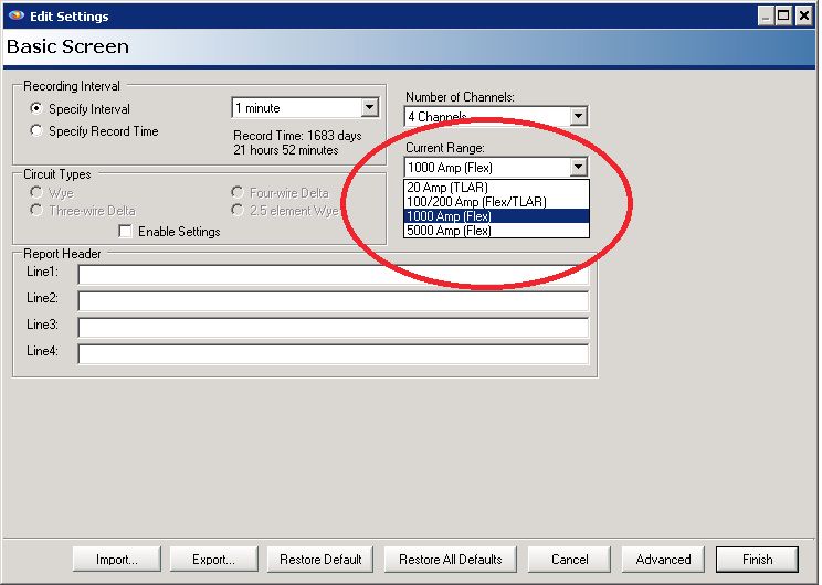
The default range is 1000A using Flex CTs, and 200A with TLARs. To change this with ProVision, use the drop-down selector to pick a new one as shown in Figure 5. If the range doesn’t match the actual clamps on the recorder, the closest possible range is used. The range can only be changed when initializing a recorder for a new recording session, or during the 2 minute countdown. After the end of the 2 minute countdown, the recording begins, and the range is locked.
