Abstract
This paper covers what a variable frequency drive (VFD) is, the different types of VFDs, their functions, and their benefits. Also covered are issues related to VFDs, some solutions to VFD issues, and how VFDs can both affect and be impacted by the power quality of the distribution system.
Components of a VFD
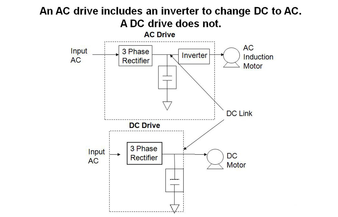
A variable frequency drive is an electronic control circuit used to control an electric motor. A VFD produces controlled pulses of voltage and current in a specific manner that controls the torque and speed of the motor. The controller is microprocessor-based, and can use real-time feedback from the actual motor load, supply voltage waveforms, desired running point and torque, etc. to more precisely control the motor startup and running operation. The main components composing a VFD are diodes, transistors, thyristors, MOSFETs, IGBTs, capacitors, resistors, and various other electronic components. Variable frequency drives are also referred to as Adjustable Frequency Drives, however adjustable or variable speed drives could be an incorrect term due to referring to a different type of control possible using belts or gears, eddy current clutches, or variable pitch sheave drives. A VFD can be used to drive AC induction or DC motors, although the basic circuit to drive these different motors will differ. A VFD to control an AC motor requires an inverter to change the rectified DC to AC whereas DC type motor does not.
Figure 1 shows the differences between the AC and DC drives; however both AC and DC drives include one more major element, a controller. An AC drive includes 4 functional elements, Rectifier, DC Link, Controller, and output Inverter.
In Figure 2, the first basic element in an AC Drive VFD is a rectifier of some configuration. Solid state diodes are the devices which are used in most rectifiers. The rectifier shown is a 6 pulse circuit, used in 3 phase systems.
The second element is the DC link. The DC link often includes an LC type filter composed of a minimum of a choke and capacitor to filter out and smooth the ripple. This helps ensure the desired voltage or current is supplied to the inverter. This LC filter also protects the output converter from voltage swells or transients.
The third element is the controller, whose function is to respond to inputs and external controls, including starting and stopping the motor, speed control, monitoring the system and reporting malfunctions and even shutting down the VFD if the malfunction is serious enough.
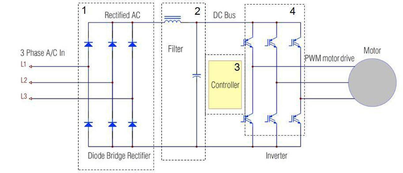
The fourth element is the inverter which changes the DC back to a variable frequency AC to control the motor speed and torque. The AC output from the inverter is not a sine wave though. Instead, a process called pulse width modulation (PWM) is used, to be explained later in this paper. The basic components of an inverter are typically silicon power switching devices such as thyristors or transistors.
Power Inversion
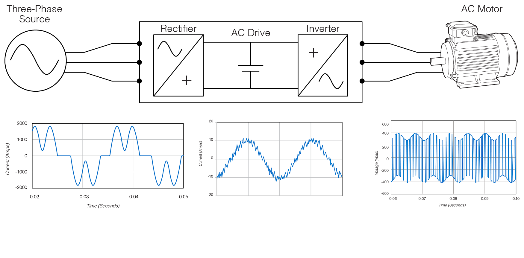
There are two basic inverter classifications or types related to power quality, the Voltage Source Inverter and the current source inverter. The voltage source inverter has a large capacitor or capacitor bank in the DC link to provide a constant DC voltage to the inverter. The voltage source inverter is usually used with smaller motors with output power up to 100 HP. Current source inverters are for larger motors over 100 HP. Rather than producing a constant voltage, they produce a constant current, and include a large inductor in the DC link to keep the DC current stable. Current source inverters generate fewer and lower levels of harmonics, and are better for overall power quality.
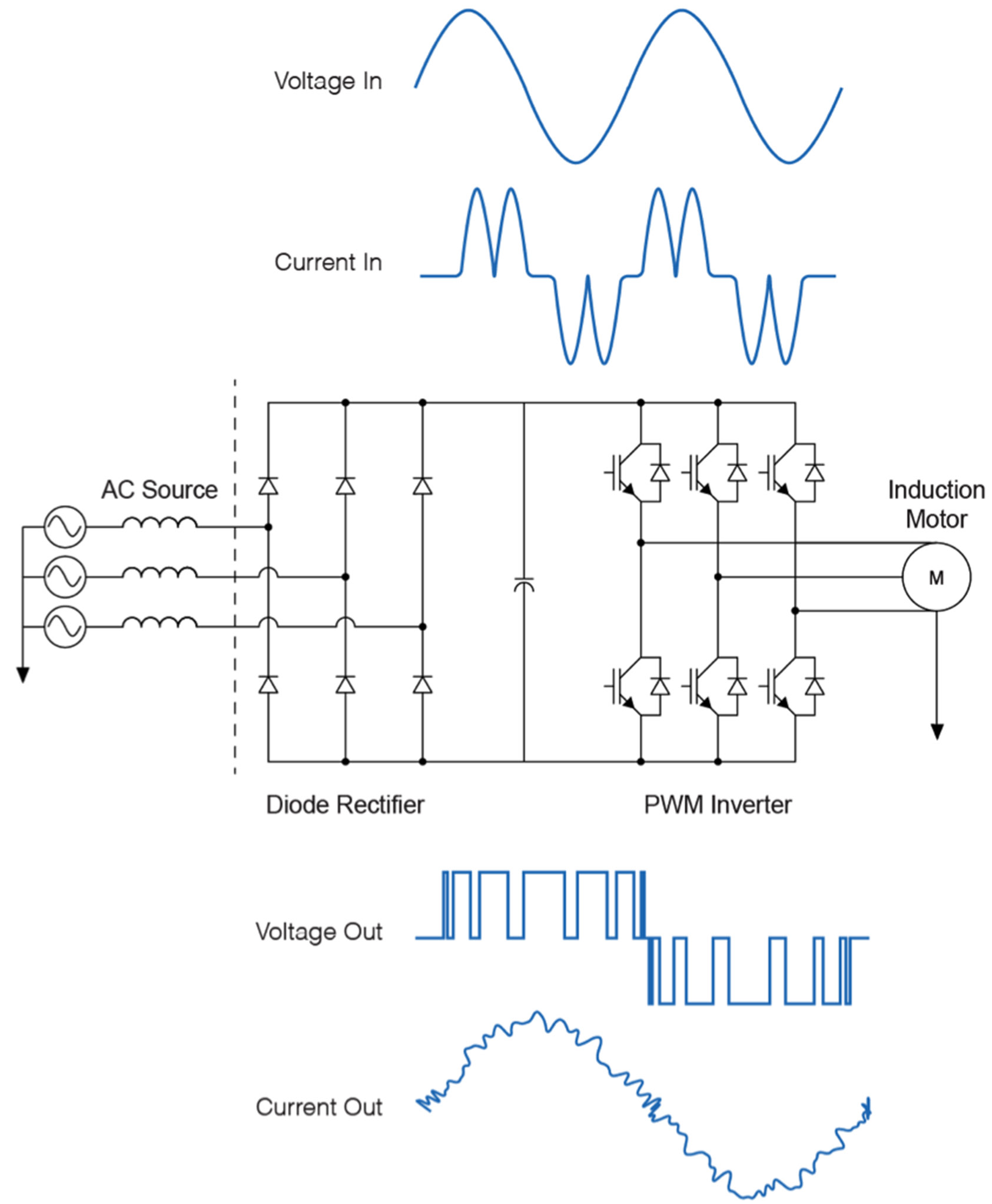
There are several classes of power inverters. Some inverters that are used in PV and wind turbine systems are classified as pure sine-wave inverters that are designed to convert a DC input into a very clean and pure sine wave. For motor speed and torque control, a sine wave is not what is needed. Instead, pulse width modulation waveforms are produced for driving the motor. Pulse width modulation (PWM) is a process used by the inverter to change the Link DC voltage into a train of pulses of varying widths.
The pulse train’s period is smaller than the 60Hz line period, and thus its frequency is much higher, usually in the kilohertz range. The train of pulses is often created by feeding a reference triangular sawtooth waveform into a signal comparator, along with the output signal. When the reference signal becomes greater than the modulation signal, the comparator output switches the output transistors on. On the other hand, when the output signal is below the reference, or “modulation” signal, the comparator will switch the transistors off (note Figure 3, below).
In a VFD DC link the input voltage is constant, and the pulse amplitude is constant over the entire frequency range. A lower motor voltage is created by using more and narrower pulses, but a higher motor voltage is created by fewer and wider pulses. Even though the voltage consists of a series of square wave pulses, the motor current will closely approximate a sine wave, due to the inductance of the motor. (Note figure 4, below.)
The inductance of the motor functions as a filter, forming the pulses into a relatively smooth AC current waveform. The voltage-to-frequency ratio remains constant from 0-60 Hertz. Depending on the microprocessor control, the output voltage and frequency will be changed simultaneously to maintain a constant voltage/Hertz ratio. At low frequencies, the output voltage will be increased. For motor drive frequencies above 60 Hz, the voltage will remain constant. Some AC drives switch from a PWM waveform to a more complex six-step waveform for 60 Hz and above.
Benefits of Using a Variable Frequency Drive
One of the main benefits of a VFD is that it saves energy, lowering the operating cost. It also has the ability to transform single phase voltage input into a 3-phase motor drive, since the input voltage is rectified and inverted back to AC.
VFDs lower the motor’s starting current. It is common for an AC induction motor to draw 6 to 8 times the full load running current when starting across the line for the first 2 to 3 seconds. Using a VFD can result in reducing the induction motor in-rush current to the point that it may never exceed full load current rating. The microprocessor drive has full control over the output drive, and can spin the motor up in a deliberate, controlled manner. VFDs are an ideal device to provide soft starts which provide the lowest in-rush current compared to other soft starter technologies such as wye-delta, part winding, autotransformers and solid state starters. The technique used by a VFD to start a motor is by first delivering power at a low frequency, then incrementally increasing the frequency and motor speed until the desired running speed is reached. By doing this the VFD reduces unacceptable voltage sags on the power system which can adversely affect other loads.
VFD can provide unlimited number of starts per hour. This is due to the ability of the VFD to reduce the in-rush current during startups so there is a significant reduction in heat, eliminating the restriction on the number of starts in a given amount of time.
VFDs isolate the system from motor switching transients, thus extending the life of the motor. The DC bus (and associated capacitance or inductance) and synthetic PWM drive decouples the motor from line voltage changes, and the line voltage from motor load changes, startups, etc. The soft startup reduces the thermal and mechanical stresses on motors and belts, again extending the life of a system. A VFD is simple to install, increases power factor, and reduces KVA. VFDs allow the use of an AC type motor in place of DC motors, which lower the cost of a given system.
Problems Produced by VFDs
One of the main issues VFD present for power quality is the creation of harmonics. Due to the non-linear input of VFDs (rectification is a very nonlinear process), they can be a significant source of excessive harmonic distortion. Harmonics originate from both the supply input and motor side of the drives, as shown in Figure 5.
Other problems related to the use of VFDs are nuisance tripping caused by sags, transients and momentary interruptions which can cause protection circuits to shut down VFDs and business production lines. Motors can sometimes overheat due to excessive eddy currents that are a result of harmonics.
Inverters in the VFD’s carrier frequency used in PWM can be in the audible range from 2 kHz to 15 kHz which can cause noise annoying employees in an industrial environment. If possible, changing the frequency to one less objectionable should be attempted. Sometimes an output choke can be used to reduce the high frequency and harmonics and audible noise. It is helpful to install the line input wires and motor cables in rigid metal conduit.
Sometimes supply voltage unbalance causes differing currents to flow in diode rectifiers, resulting in unequal diode heating which could lead to nuisance tripping, or eventual rectifier failure. To keep this from continuing to happen, improved load balance is needed. Conversely, an unbalanced current draw from a VFD is a sign of a diode failure in the rectifier block, or impending failure. Manufacturers typically specify the cable not to exceed 100 feet from the VFD to the motor being powered. Due to fast rise times and switching speeds used with PWM systems, high frequency ringing and reflections can result in high voltage transients which can actually puncture the insulation or exceed the peak inverse voltage rating of the semiconductor devices used in the inverter. Many manufactures are now requiring inverter duty motors to be rated for 1.5 kV so they are able to withstand switching overvoltages when they are used with VFDs.
In addition to producing some PQ issues, VFDs can be sensitive to PQ problems. The VFD controller may sample the AC input waveform, and intentionally shut down the motor if the waveform is out of tolerance. The parameters for motor shutdown are often set very conservatively from the factory. These settings can cause nuisance motor shutdowns when no actual problem is present. Working with the customer to help reprogram the controller to be compatible with normal line voltage events can help resolve this type of issue.
Guidelines and Tips for Monitoring VFDs
The key parameters in a VFD investigation are RMS voltage and current, harmonics, voltage unbalance, and waveform capture (Figure 6). Connect the recorder in the same configurations as the VFD. In other words, if the VFD is wired as a delta, connect the recorder as a delta. Make sure to disable unused channels to maximize the recorder’s memory. Event captures is also useful for sag detection, and remember to set the nominal voltage as close as possible to the nominal system’s voltage for best results.
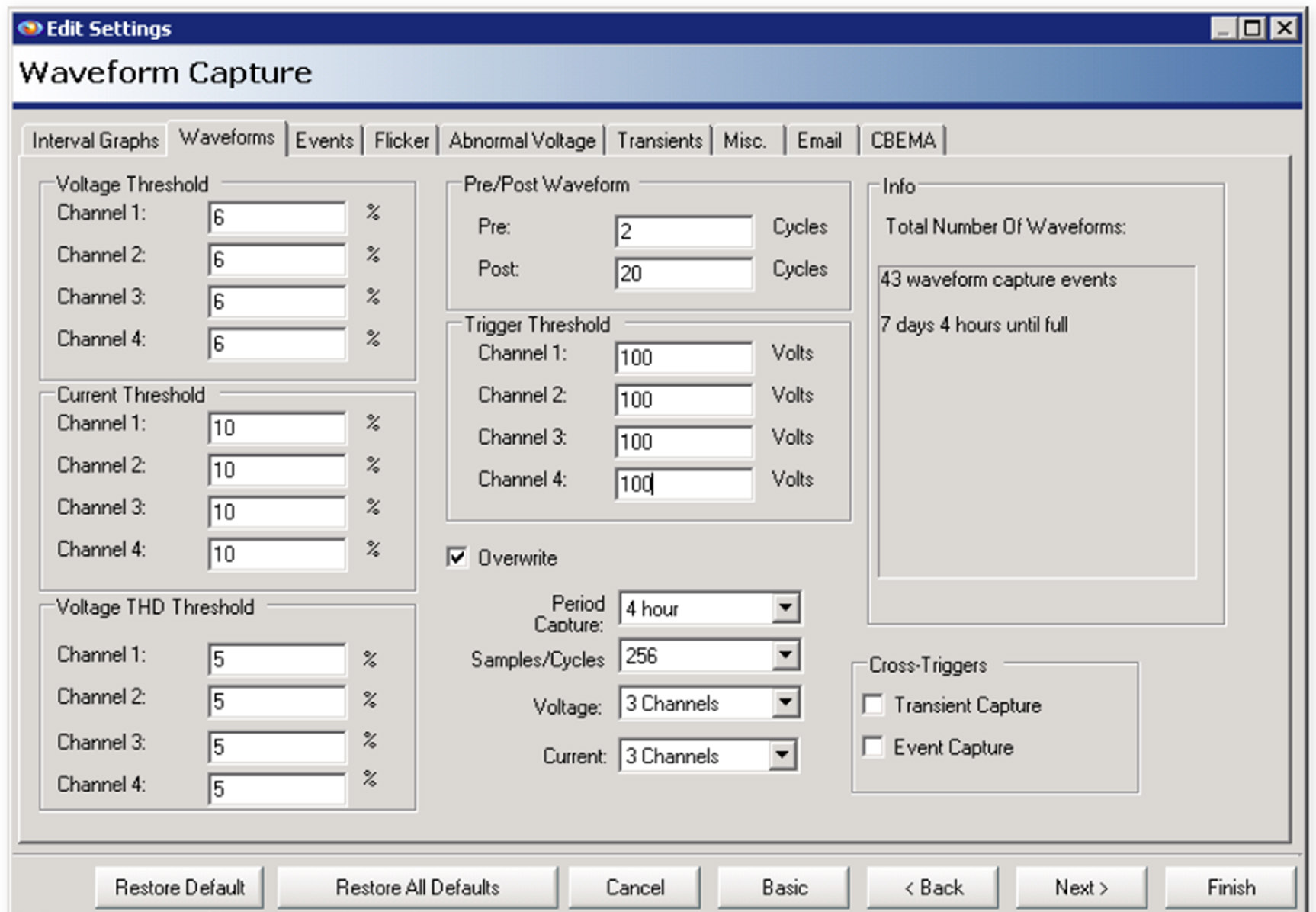
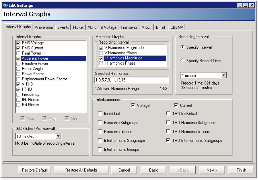
Install the monitor’s voltage leads and current CTs on the power input conductor at the VFD AC power input. Turn on voltage, current, VTHD, ITHD interval graphs (Figure 8), and the periodic waveform capture feature. It is important to make sure that the current range on the CTs is set appropriately (e.g. 100A or 1000A range) for the actual VFD current for accurate measurements. Under the Harmonics voltage and current magnitude setting, enable the odd harmonics from the 3rd through the 15th. With a Revolution, also enable the “THD Interharmonic Subgroups”, to see if there are interharmonics present. If the motor is running most of the time, a periodic waveform capture could be useful for obtaining a “normal” snapshot. For a quick motor start recording, use a 1-cycle stripchart interval, and record a few motor starts and stops. It’s also possible to use a very long waveform capture (10 or more seconds) for a very detailed motor start investigation.
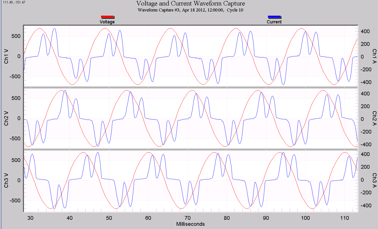
A typical VFD voltage and current waveform capture is shown in Figure 7. This is a 6-pulse voltage source inverter, as shown in Figure 4. The diodes in the rectifier block conduct current from each phase for the fraction of time that each phase is above the DC bus voltage. This happens as each phase goes through a positive and negative peak, for a total of 6 pulses in each 60Hz cycle. Some current imbalance is visible here. Normally each current pulse is approximately the same height, but an incoming voltage unbalance will cause unequal currents in the diodes. Also, a failing diode or bad connection can cause current unbalance.
Solutions for Resolving VFD Harmonic Problems
VFDs have many positive attributes; however without some safeguards they can be problematic to power quality due to their nonlinearity. To reduce harmonic production, it may be necessary to employ filtering such as traps, line reactors or isolation transformers, as shown in Figure 9. Some other solutions may be to increase the size of the neutral conductor. The use of VFDs with larger 12 or 18 pulse converters also reduces harmonic generation. Detuning circuits by changing capacitor bank sizes and employing phase shift cancellation by use of both delta-delta and delta-wye supply transformers can also reduce the severity of a specific harmonic problem.
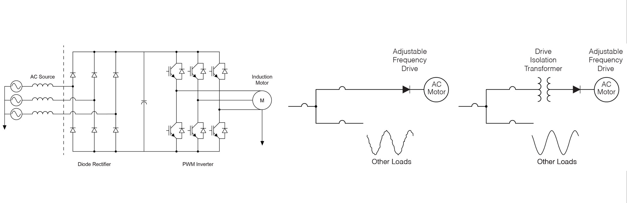
- Install Line Reactors
- Install Drive Isolation Transformer
- Drive Isolation Transformers Reduce Harmonic Distortion Effect of VFDs
Conclusion
There are many benefits to using VFDs, both for the end user and the utility. For the user, extending equipment life and reducing maintenance along with energy savings are important, not to mention that VFDs allow for precision motor control difficult or impossible to achieve in other ways. Greatly reducing the in-rush current results in less voltage sag production for the utility. With proper implementation, filtering, and monitoring, it is possible to keep the power quality issues that VFDs can present on the power grid under control.
