Abstract
Transformer loading is ultimately limited by internal heating caused by load current flow. Some heating is caused by resistive losses in the transformer winding. Another important heating source is eddy current. There are several other factors that also contribute to transformer heating, such as hysteresis in the steel, skin effect in transformer windings, and the temperature effect on the copper winding resistance (increasing the copper’s resistance when the transformer begins to heat up).
Traditionally, a transformer volt-amp (VA) rating could be used for transformer sizing, with the VA rating based on 60 Hz load current heating. However, a nonlinear waveform contains harmonic components (frequencies at multiples of the 60 Hz fundamental). All of the heat sources mentioned tend to worsen as the number of harmonics and the harmonic magnitudes increase. For some effects, the amount of heat generated per amp of current increases dramatically at higher frequencies.
K-Factor
K-factor is derived from ANSI/IEEE C57.110. K-factor is a metric designed to quantify transformer heating due to nonlinear current waveforms, taking into account increased heating from harmonics. K-factor can be defined as a weighting of nonlinear harmonic currents, based upon how they affect the heating of a transformer in comparison to a pure sinewave. K-factor is used to de-rate transformers to provide them with enough head room capacity to keep from overheating.
K-factor is calculated by the following equation:
K-factor = Σ(h=1 to hmax) I²h × h² / Σ(h=1 to hmax) I²h
“h” is the harmonic number (1 = fundamental, 3 = 180 Hz, etc.). Ih is the harmonic magnitude for harmonic h. The formula reveals three points to remember. First, the K-factor increases as the square of the current. A doubling in current gives a K-factor 4 times larger. Second, the K-factor increases as the square of the harmonic number. A load of 2 amps at 180 Hz (3rd harmonic) produces 9 times the heating of 2 amps at 60 Hz! The heating effect dramatically increases due to the square of the harmonic factor. Third, the K-factor is scaled by the square sum of all the Ih current measurements, making it a unitless value independent of total RMS current.
Power transformer heating occurs over a relatively large amount of time since they are large devices with high thermal mass. With steady state current, the transformer temperature will rise until reaching its thermal equilibrium, where the amount of heat the transformer is producing equals that radiated into the surrounding environment. This equilibrium temperature will be higher on sunny or hot days.
The key is to ensure that the equilibrium temperature is well below the point where the transformer’s insulation begins to degrade or break down. Transformer size should be matched to the peak load current and the load’s harmonic content. If the harmonic content is not considered the transformer may fail prematurely. Short term increases in power will increase the transformer’s heating, however if these are not too long or severe, the transformer’s large thermal mass will slow the heating and avoid damage to the transformer.
Computing & Analyzing K-Factor with ProVision
Because of the large thermal mass, K-factor measurements should be taken only during steady state waveforms. ProVision computes K-factor from waveform data, and transients or other anomalies should be avoided for this analysis. When using ProVision, slide the grey cycle selector to a place where a normal looking waveform is found. For captures triggered on a periodic basis, any cycle may be suitable. If the capture was triggered on a disturbance, it is better to look for a “normal” looking cycle before or after the triggered portion of the capture to make the best K-factor measurement.
Another important tip when making K-factor readings: don’t be too concerned about a high K-factor measurement if the RMS current is low. A highly distorted current waveform may have a high K-factor mathematically, but if the total RMS current is low compared to the transformer size, the absolute heating may still be low. High K-factor becomes more important as the RMS current (or total volt-amps) approaches the transformer nameplate rating.
Here are the steps to analyze K-factor with ProVision:
- To load the file of interest into ProVision, use the File, Open command then find and left click on the file’s name.
- Along the top of ProVision, go to Graph, and left click, which brings down a vertical graph menu.
- Scroll down to Harmonic Analysis, and select Magnitude. This will launch the captured waveform list (see Figure 1, Provision Waveform Selection).
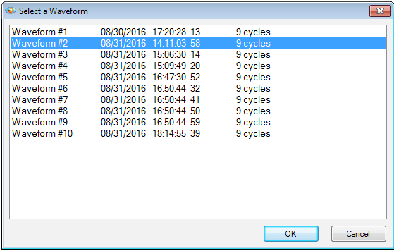
- Select one of the Waveform captures. In Figure 1 above Waveform #2 is selected.
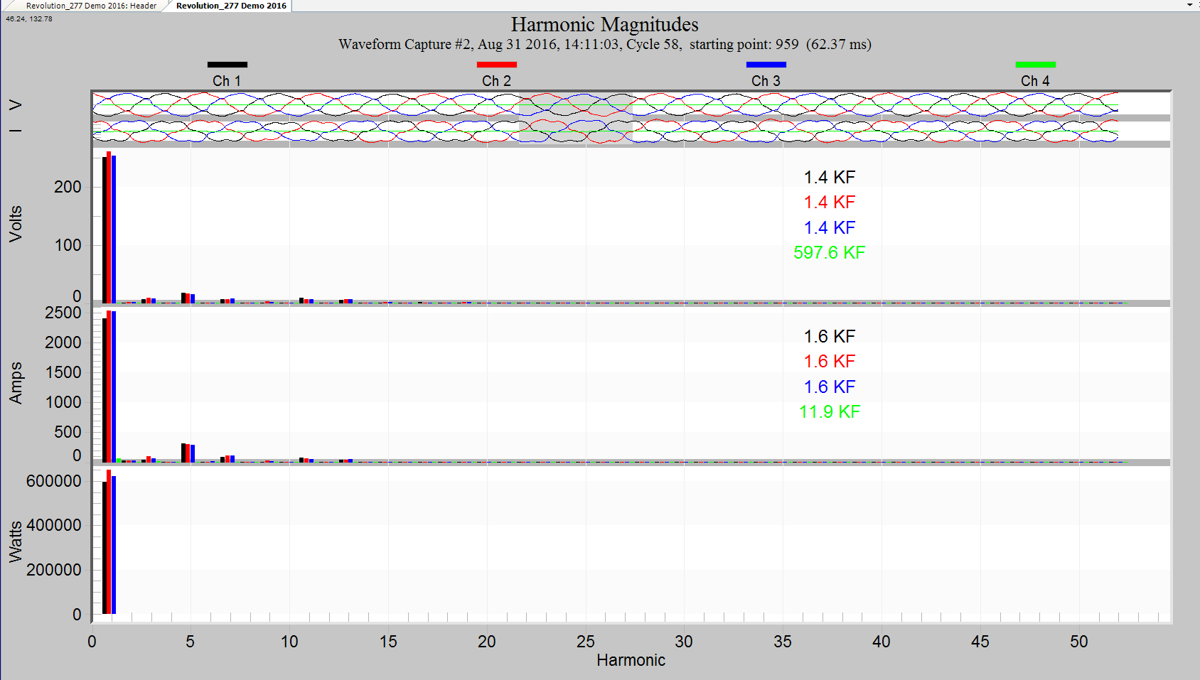
- Move the mouse pointer over the THD-F percentage and click the left mouse button 4 times until the KF, K-factor appears. The labels should change from THD-F, to THD-R, TIF and then on the fourth click, to KF or K-Factor (see Figure 2, Harmonic Magnitudes Graph with K-factor Selection).
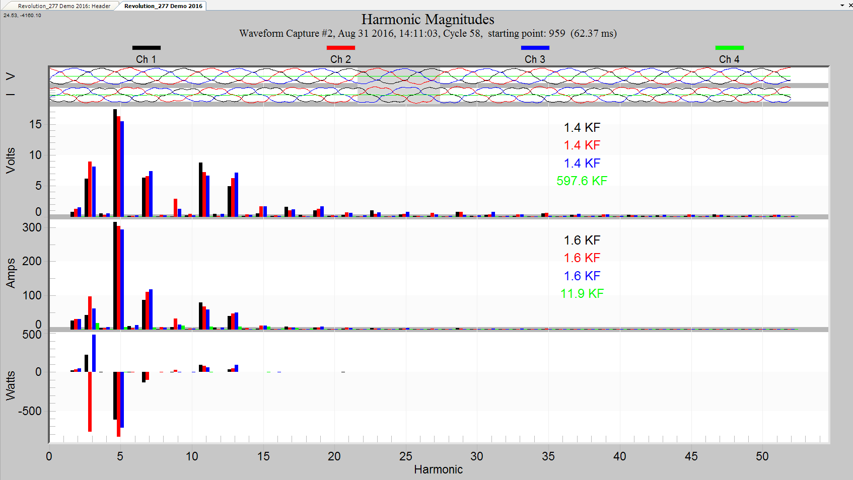
- Move your mouse to the gray bar at the top of the graph. Depress the left mouse button and slide the gray bar at the top moving the mouse to the right. The gray bar represents a single cycle of data from the captured waveform. Select a cycle that is most representative of the steady state load on the transformer.
- Notice that (see Figure 3, Harmonic Magnitude Graph without fundamentals) under the Current Graph, Channel four has very little current flowing, thus very little power or ability to contribute heat to the system. This 11.9 KF should be disregarded. Instead, focus more on the 1.6 KF in Channels 1, 2, and 3. Channel 4 is typically a neutral current, and K-factor is not designed for this type of measurement point.
Summary
Tips when making K-factor measurements:
- Make your measurements in a “normal” steady state waveform cycle, before or after a waveform transient.
- Periodic capture waveforms are preferred for K-factor calculation.
- Pay attention to the amount of current (RMS value) that is involved in large K-factor measurements. If the current is low compared to the 60 Hz transformer rating, the K-factor may not be an issue.
- Infrequent and short lived mild surges and waveform anomalies rarely add much to transformer heating. Five or even 15 minute averages are appropriate when analyzing RMS current for transformer heating.
Proactive monitoring of transformer load should be performed to detect excessive heating that eventually causes the transformer to fail. If a customer is planning a large expansion or load increase, before and after measurements should be performed. Usually when a transformer fails, it happens very suddenly, interrupting customers and requiring immediate attention. A proactive approach is always better than having to put out fires.
