Abstract
The settings configuration window is a new feature in PMI’s Canvass web software. It allows the user to set thresholds for each channel and measure supported by the recorder. When used in conjunction with the e-mail alerts window, it allows users to configure their recorders to send e-mails when a trigger threshold has been crossed. This paper will explain the different thresholds and how to set them.
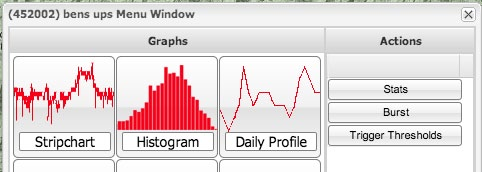
To begin editing thresholds, open the menu window of a recorder. This can be done by clicking on the recorder on the map or by selecting it from the list in the left of the application interface. If the recorder supports trigger thresholds, a button labeled “Trigger Thresholds” will be visible on the right hand side of the recorder’s menu window (Figure 1). Click on this, and the Trigger Thresholds window will appear (Figure 2). The window will initially be masked out as it loads initial or previously applied thresholds from the device. If this process fails, an alert will pop up and the window will close.
If the thresholds are successfully downloaded from the recorder, the window will be unmasked, allowing input into the threshold fields. The thresholds are organized into tabs, voltage thresholds, current thresholds, power thresholds, etc. Depending on the type of the recorder, some of the tabs may be hidden. A Revolution will have all tabs editable. The list of available tabs is: RMS Voltage, RMS Current, Power, Phase Angle, Power Factor, THD, Pst, Total Measurement, and Global Parameters.
Most thresholds are broken up into four fields: low-low, low, high, and high-high. The low field represents a value that would be considered low for the monitored source. Low-low would be a value that is lower than low and would be cause for alarm. Similarly, high would be a high value for this measurement, and high-high would be an unusually high value.
Click on the RMS Voltage tab to begin editing values for RMS Voltage. A spreadsheet like grid will appear, with the columns representing the different threshold states (low, low-low, high, and high-high) and the rows representing each channel of the recorder. To edit a value, double click on the cell where it is represented. This same channel / measure format is repeated for the Current, Power, Phase Angle, Power Factor, THD, and Pst tabs. Setting any of these fields to 0 will disable the alarm.
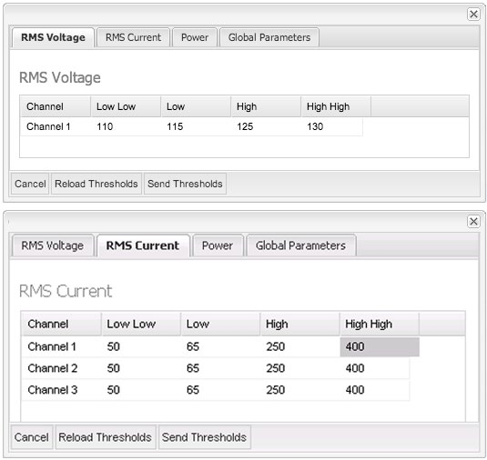
For voltage thresholds, values should be set around the expected nominal voltage. A common setup is +/- 5% for low thresholds and high thresholds, and +/- 10% for low-low thresholds and high-high thresholds. For example, the thresholds with a nominal at 120V would be 108, 114, 126, and 132V. For current and power, the settings depend on what the intent is. To trigger on when a load disappears, set the low values below the smallest load current. For monitoring when a load switches on, set the high thresholds below the load current.
The “Global” tab (Figure 3) contains two parameters that affect all the thresholds: Holdoff Time and Hysteresis. The Holdoff Time is the duration that a trigger condition must be continuously met before an alert is declared. If the measured quantity crosses a threshold limit, then returns to normal before the Holdoff Time elapses, then an alert is not generated. Using this setting prevents false triggering on momentary events, for example setting it to 300 seconds (5 minutes) for voltage will avoid triggering on short-term voltage sags from motor starts, etc., but still catch steady-state under-voltage conditions for end-of-line monitoring.
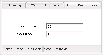
Hysteresis is a parameter that introduces a direction-dependent offset to the trigger thresholds. Its purpose is to prevent “chattering” if the measured quantity is hovering around a threshold. For instance, if the voltage is close to a threshold value of 108.0V, but wandering up and down from 107.9V to 108.1V, using hysteresis will avoid multiple events being triggered. A value of zero disables hysteresis.
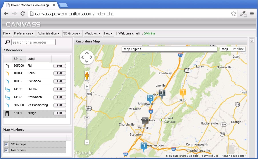
When finished editing thresholds, click on the button labeled “Send Thresholds” located in the toolbar at the bottom of the window. Clicking “Refresh Thresholds” will reload thresholds from the device. This is useful after thresholds have been sent and confirmation is needed that the thresholds did change. When a recorder threshold is triggered, the map marker in Canvass representing the recorder will change to orange as shown in Figure 4.
Setting E-mail Alerts
Once trigger thresholds have been set, e-mail alerts may be set to actually receive alarms from the device. E-mail alerts are configured as “distribution lists”. In the event that one of the thresholds is triggered, if configured, an e-mail will be sent to the e-mail address of the selected user. To begin configuring e-mails, click on the “Administration” button on the application’s main toolbar. From there click “E-mail Alert”. The distribution list window will appear. To create a new distribution list, click “Add List” located at the top of the window. In the window that appears, type the list’s name and click “OK”. The distribution list will be saved and will appear in the grid in the distribution list window.
Setting Distribution List Alerts
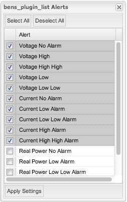
Find the row corresponding to the desired distribution list and click on the “alerts” button. The alerts window will open as shown in Figure 5. Select the alerts that you would like in the distribution list by clicking on the checkbox next to the event’s name and click “Apply Settings” to save them. Available alerts are: voltage low, voltage low low, voltage high, voltage high high, current low, current low low, current high, current high high, power low, power low low, power high, and power high high. In any of the distribution list windows, clicking “Select All” and “Deselect All” at the top of the window will select and deselect all items, respectively.
On the distribution lists window, click recorders next to the desired distribution list. In the window that opens, select the recorder that trigger thresholds have been set on, and click “Apply Settings”. Multiple recorders can be added to the same list, though it is important to set the trigger thresholds for each recorder that is added.
Going back to the distribution list window, click on “E-mail”. Select the users that should receive trigger threshold e-mails from the previously selected recorders. Click “Apply Settings” to save the changes.
Conclusion
With Canvass, you can use your web browser to configure simple or complex voltage, current, or power triggers in Boomerangs, and define email distribution lists for single or multiple events. Canvass also shows at a glance which Boomerangs are currently under an alarm condition. The Boomerang and Canvass together create a powerful web-based monitoring system.
