Introduction
Three-phase power systems are the standard for electrical distribution in industrial and commercial applications. Delta systems often have unbalanced loads making it mathematically impossible to accurately measure the power and power factor for individual phases due to the unequal distribution of current and voltage across the phases. Unlike balanced loads, where the current and voltage are symmetrical, an unbalanced load causes each phase to operate under different conditions, leading to variations in phase voltage and current. These currents are not accessible outside the delta.
As a result, traditional per-phase power measurements are not possible, even though the total three phase power is still computable. This method is shown here.
What Is a Three-Wire Delta System?
A three-wire system delivers power through three energized conductors, with voltages that are 120 degrees out of phase from each other. The delta connection, often represented as a triangle (Δ), is a configuration used in three-phase electrical systems where each of the three phase windings are connected end-to-end in a loop, forming a closed loop (Δ).
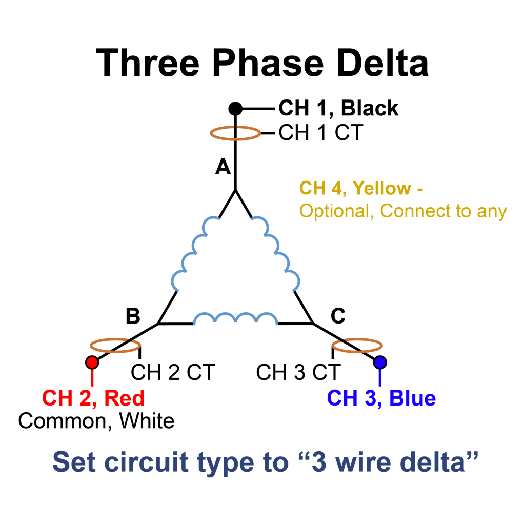
In this setup, the line-to-line voltage is directly applied across the windings, meaning that the phase voltage is equal to the line voltage (VL). Each corner of the triangle is a connection point for the line wires. There is no central neutral point unless one is artificially created with a ground reference.
Delta connections provide higher starting torque (due to the higher voltage compared to wye circuits) and are typically used in heavy machinery, such as three-phase induction motors. They are widely used in industrial settings due to their ability to handle high power loads and allow for easy addition or removal of loads across phases.
The smaller phase currents for a given power in the delta systems give them an advantage in efficiency, reducing conductor size and minimizing losses.
Types of Loads in Delta Systems
In a three-phase delta system, the type of load connected to the system plays a crucial role in determining the behavior of the system and the corresponding power readings. Loads in a delta system can generally be classified into three categories:
- Balanced Loads
- Unbalanced Loads
- Specific types of resistive, inductive, and capacitive loads
Balanced Loads
This is the ideal scenario for a delta connection. A balanced load means that each of the three phases carries the same amount of current, and each phase is at the same voltage. Under balanced load conditions, the system operates efficiently, with the three-phase power evenly distributed across all three phases. This results in symmetric power readings from the PQ recorders, where the readings for each phase are consistent, and the total power consumption can be easily calculated using standard formulas.
Unbalanced Loads
In practice, unbalanced loads are common, especially in industrial environments. An unbalanced load occurs when the impedance in one or more phases is different, leading to unequal current or voltage in the phases. This could be due to faults, mismatched components, or variable load conditions. Unbalanced loads introduce complexities in power measurement, as the power readings from the PQ recorders will differ across phases, leading to a more complicated analysis. In these cases, additional measures such as harmonic analysis or load balancing techniques may be necessary to ensure stable operation and accurate power readings.
Resistive, Inductive, and Capacitive Loads
Delta systems are used to supply a wide variety of loads, each affecting the system’s power factor and overall power consumption. Resistive loads (e.g., heaters) consume real power without introducing phase shift between voltage and current. Inductive loads (e.g., motors, transformers) introduce a lagging power factor, causing the current to lag behind the voltage. Capacitive loads (e.g., capacitor banks) can lead to a leading power factor, where the current leads the voltage. The nature of the load affects both the reactive power and apparent power in the system, which must be accounted for when performing power measurements in a delta connection.
Why Do Power Measurements Only Show Channel One on PMI PQ Recorders?
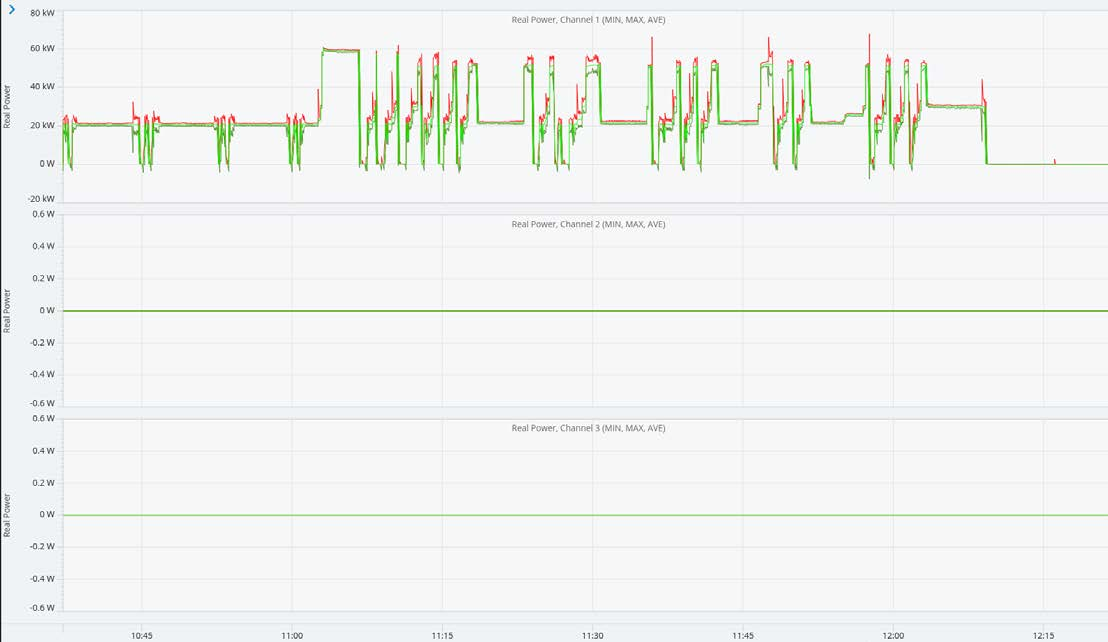
With a three-wire delta circuit, individual phase powers and power factors cannot be computed without imposing assumptions such as a balanced load, balanced source, etc. In a three-wire delta system with an unbalanced load, it becomes challenging to accurately measure the power and power factor for individual phases due to the unequal distribution of current and voltage across the phases. Unbalanced loads cause each phase to operate under different conditions, leading to variations in phase voltage and current. Only total quantities can be computed in this mode.
These values are computed and recorded as channel one data.
In a simple single-phase situation, the RMS voltage and current (Vrms and Irms), real power (W), reactive power (VAR), apparent power (VA), power factor (PF) and displacement power factor (DPF) are straightforward to calculate (see the white paper Formulas for Power and Harmonic Measurements for the details).
Real power represents the actual power consumed by a load, reactive power is power transferred to and from the utility in a single cycle (but does no net work), and apparent power is the burden seen by the distribution system to deliver the real power (the power “apparent” to the wire, transformers, etc.)
Power factor is the ratio of real to apparent power with 1.00 being perfect. The displacement power factor (DPF), is the power factor of just the 60Hz portion of the waveform. These formulas can be extended in the case of a three-phase Wye, since each phase may be treated separately, and a three-phase total computed from the individual phases. In a three-phase delta, there is not enough information that can be measured to do this.
With a three-wire delta, there is no neutral connection, and it’s impossible to measure current “inside the delta”. Since the measured currents are the vector sums of the line currents inside the delta, and there are only two unique voltage readings (the third by definition can be computed from the other two) there is information that is lost that can’t be recovered mathematically.
From Blondel’s theorem, the “two-wattmeter” method may be used to correctly calculate total real power, but it’s not possible to uniquely determine the individual phase power readings.
Conclusion
Three-phase power systems are the standard for electrical distribution in industrial and commercial applications. Since delta systems’ power readings for individual phases cannot be computed without imposing assumptions, Power Monitors PQ recorders give total power measurements on channel one.
