Abstract
This paper describes what skin effect and proximity effect are, how they influence electric power transmission, and what steps are taken to reduce their losses.
Skin effect is a phenomenon that occurs when an alternating current flows through a conductor, causing the current density to decrease exponentially between the surface toward the center of the conductor. With DC current, the current flow is equally distributed through the entire conductor cross-section. In other words, the current density is the same in each volume of the wire. With AC current, the distribution is not uniform – instead, current tends to concentrate closer to the surface of the conductor. As the frequency increases, the current density depth in the conductor decreases, which causes the effective conductive cross-sectional area to be reduced. This effectively increases the electrical resistance of the wire with AC current, over that of direct current for an identical conductor.
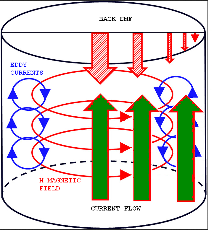
The AC or alternating current in the wires produces an alternating magnetic field in and around the wire itself. The magnetic field intensity is directly opposed to the current flowing through the wires. As the intensity of the current changes during a cycle through the sine wave, so does the intensity of the magnetic field. The conductor’s permeability (the degree to which the conductor can be magnetized) influences how quickly the magnetic field can be changed. The conductor’s permeability in the magnetic field, in turn, creates an opposing current in the wire and eddy currents during the phase reversal, sometimes referred to as a back EMF.
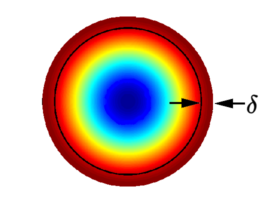
This phenomenon at AC frequencies, due to the eddy currents produced, acts like a mirror to electromagnetic fields restricting the field from penetrating the conductor. As the frequency becomes higher, the mirroring effect becomes more pronounced forcing the current flow closer to the surface of the conductor. This reduces the conductive cross sectional area. The electromagnetic penetration into a conductor is referred to as the skin depth. By definition, this is the depth into the conductor that the current falls to 1/e, or 37% of its surface density.
This causes the current flow on the surface of the wire to be less impeded than it would be flowing closer to the center of the wire.
At 60 Hz the skin depth for copper wire is about 8.61 mm or about 1/3 of an inch. Almost all of the current, over 98%, will flow in the top four skin depths, leaving less than 2% to penetrate any deeper. A 2000 MCM copper conductor’s resistance is 23% higher at 60 Hz than at DC.
The difference between DC and AC resistances is higher with poorer conductors, such as aluminum. Ferromagnetic materials such as iron are dramatically worse, due to their high magnetic permeability. Iron’s skin depth at 60 Hz is just 0.0087 inches, making it useless for AC power transmission.
Most wire conductors for transmission lines are aluminum which has a skin depth of 0.43 inches, not much greater than for copper. For long spans, most transmission lines use a steel-reinforced center core, abbreviated as ACSR (Aluminum Conductor Steel Reinforced). Since most of the current flow is on the outside aluminum conductor due to skin effect (especially with steel’s very low skin depth), the steel core adds strength without much effect on the wire’s overall AC resistance or impedance. ACSR does have a steel core which introduces some undesirable magnetic hysteresis losses. With the proper design using an even number of aluminum layers in the conductor, these hysteresis losses can be minimized. This is a result of magnetic field cancellation by opposing wire lays; one conductor is wrapped in the right-hand direction and the other in the left-hand direction. Hysteresis losses cannot be avoided in the smaller conductors with standard ACSR cable due to having just one layer. These cables cannot carry as much current in proportion to their size as compared with even layer designs.
The total strength of the ACSR cable is dependent on the tensile strength of the aluminum, so this limits the operating temperature to 75 °C. At this temperature the aluminum starts to become soft and loses some tensile strength. Another type of cable, ACSS or aluminum-conductor steel-supported cable, can be used up to 250 °C. This is because the ACSS relies mainly on the strength of the steel for support and not the aluminum.
Aluminum is not as good of a conductor as copper or silver, but the weight, strength, and cost make aluminum or reinforced aluminum the most economical solutions for the long runs. The most economical size and type of the conductor is usually determined by Kelvin’s Law. Kelvin’s Law states, “the most economical size of a conductor is that for which annual interest and depreciation on the capital cost of the conductor is equal to the annual cost of the energy loss”. Skin effect and cable design do play a part in those energy losses.
Many concerns about skin effect are from technologies that deal with higher frequencies, such as audio and RF, where the higher frequencies make the effect more pronounced; however, even at power line frequencies, the losses can be significant on long transmission runs.
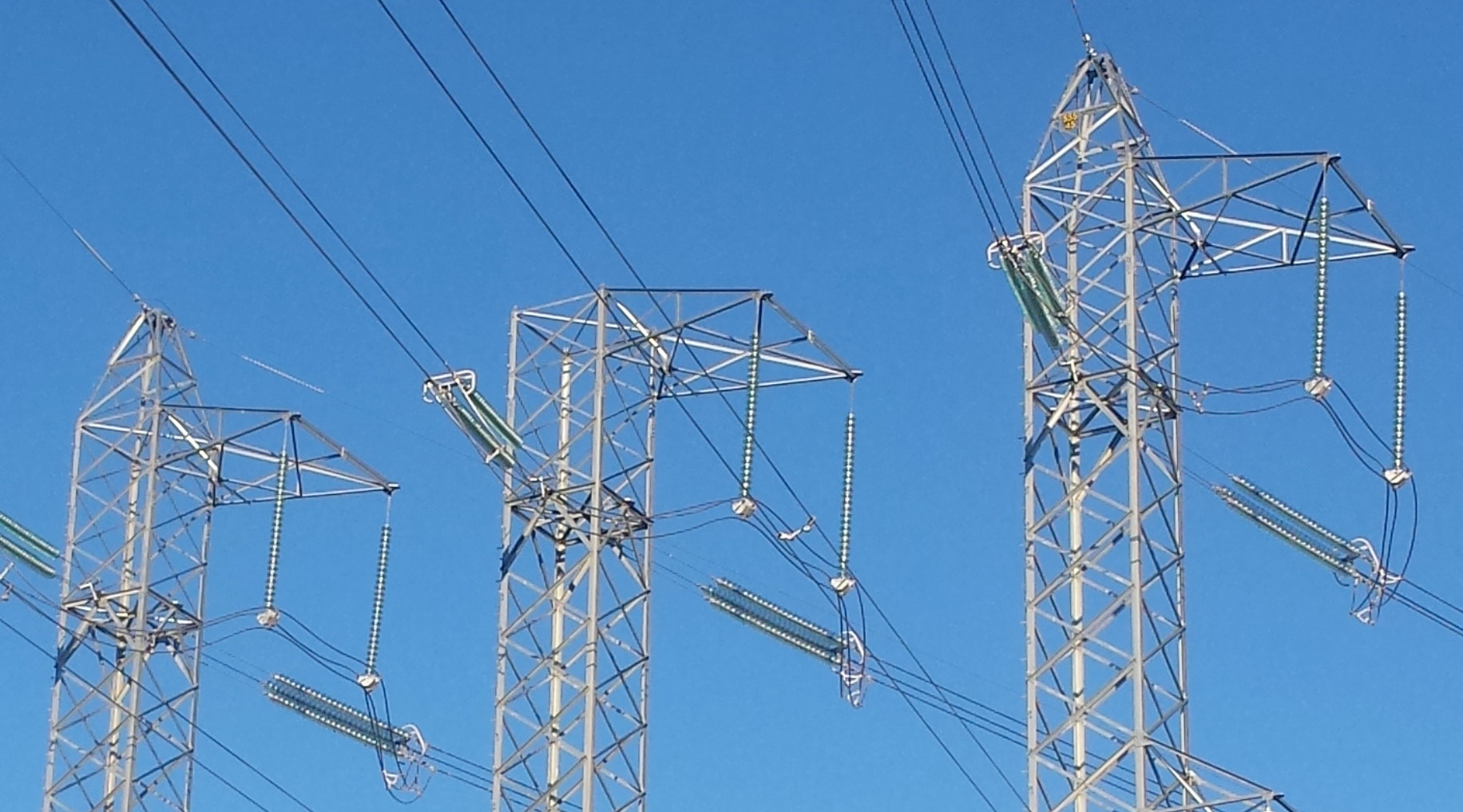
On high power transmission lines, it is a common practice for more than one conductor to be used per phase, allowing a reduction of each wire’s diameter. This helps reduce skin effect losses for the same amount of total material used.
Another effect that is very closely related to skin effect is the proximity effect. This effect happens when two or more AC-carrying conductors are placed close to each other so that their magnetic fields interact. The varying magnetic field from one conductor induces a field into the adjacent conductor. This magnetic field causes a redistribution of the current in both wires, causing more current to flow on the wire’s side facing away from the other wire. Each conductor affects the other in mirror fashion. This redistribution of the current in the wires increases the AC resistance from the DC value.
On high voltage power transmission lines, a technique is sometimes used called bundling. With bundling, more than one conductor is placed in parallel, spread apart with a spacer. This bundling of wires causes the power transmission to be more efficient due to several factors. The surface-area to mass ratio is improved, which lowers skin effect losses and corona effect. The overall capacitance is also increased, thus increasing overall power factor. Separating the conductors reduces the proximity effect resistance increase. The separation also reduces the voltage gradient on the line, which allows the conductor to operate at a higher voltage air ionization to the point of causing corona discharges. These corona discharges cause power losses and also create audio and radio frequency noise.
Skin effect and the closely related phenomenon called the proximity effect discussed earlier, do cause losses in power distribution systems. Even at the relatively low 60 Hz frequencies, the proximity effect can cause substantial losses, but these losses can be reduced by ensuring the lines are separated from other metal objects or other conductors. Also, it is important to minimize the number of tight radius bends which can compound the proximity coupling between the conductors. These same design guidelines also tend to reduce the skin effect and corona discharge likelihood at the transmission level.
When non-linear loads are present on the power system, they introduce harmonics onto the system. These harmonics are multiples of 60 Hz, and the higher frequencies result in much more pronounced skin effect issues, especially for transformers. Not only does the skin effect reduce the effective cross sectional area, causing the effective resistance to increase, but the extra heat generated from higher resistance compounds the problem increasing resistance further due to the large, positive temperature coefficient of copper.
In power transmission transformers, proximity effect accounts for more of the loss than simple skin effect. In some transformer designs, measures are taken to reduce the proximity and skin effect losses. For example, using foil instead of round wire reduces the losses in a transformer. Interleaving the windings decreases the effective number of layers in each winding section. This allows the resulting field to rise more gradually than in a non-interleaved winding, causing the field to be more uniform, reducing the proximity effect.
Conclusion
At DC and AC, the resistance of a conductor is inversely proportional to the “effective” cross sectional area of a conductor. With AC however, the skin effect causes the effective cross sectional area to decrease, thus causing the resistance to increase as the frequency increases. Skin depth is inversely proportional to the square root of the frequency. At power line frequencies, these losses are fairly small but need to be considered for long high power transmission lines.

There are four major factors that affect the skin effect losses. They are the conductor’s permeability (which is determined by the conductor material), the AC frequency, the diameter of the conductor, and the shape of the conductor. Proximity effect compounds the losses by reducing the effective cross sectional area even more than the skin effect losses alone.
