Abstract
There are three primary recording types for harmonics in PMI recorders: stripcharts, daily profiles, and waveform capture harmonic analysis. Each of these has specific pros and cons, and setup considerations to optimize the data gathered during a recording session. These are discussed below, and recommendations are given for different situations.
Interval Data
Any PMI recorder with harmonic capability can record stripchart trend data of any specific harmonic. Like the standard RMS voltage and current stripchart data, each selected harmonic is recorded at the stripchart interval period, with a min, average, and max value logged. Unlike the RMS values, the harmonic min and max readings are one second values, not one cycle values, to reduce the influence of short-term changes to the harmonic values. For example, with a 1 minute interval, each selected harmonic will be logged every minute, with the 1 minute average, and 1 second min and max values. The specific harmonic numbers to log are chosen in ProVision during the recorder setup. In Figure 1, the ProVision setup screen is shown, with the harmonic selection box circled in yellow. Enter the specific harmonics to be logged separated by commas, or enter a range. For example, the odd harmonics to the 9th would be entered as “1,3,5,7,9”, or all through the 7, plus odds to the 15th would be “1-7,11,13,15”. A “1” is the fundamental, and it’s recommended to record that along with any others, especially for current Total Demand Distortion applications.
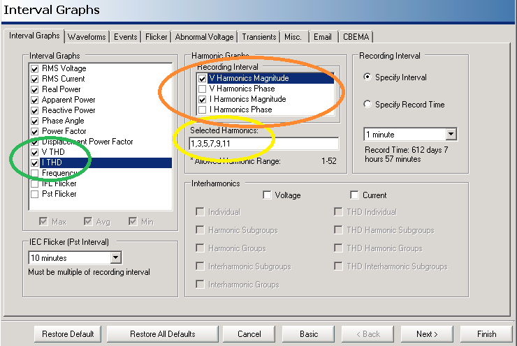
The orange circle in Figure 1 denotes the section where the harmonic types are enabled. Voltage and current (V and I) magnitude and phases may be selected. Normally just the magnitudes are important, so it’s recommended to not record phase angles except for very specific applications. If voltage THD is not a problem, just the current magnitudes could be recorded. The harmonic numbers selected in the yellow section are applied to each checked measurement type – e.g. for the settings in Figure 1, the odd harmonics through the 11th will be recorded for both voltage and current magnitude, for all channels enabled on the main settings page.
Enabling many harmonics can consume a large amount of stripchart memory. For a four channel recorder like the Eagle 440, recording all 51 harmonics for voltage and current magnitude and phase results in 51 harmonics x 4 quantities (V, I mag, phase) x 4 channels x 3 types (min, ave, max) = 2,448 separate stripchart traces! Recording just magnitude, and just the lower odd harmonics brings this to a more reasonable number. If all harmonics are needed, or both magnitude and phase, then a 1GB Revolution may be more suitable, or the waveform capture harmonic technique described below.
In addition to individual harmonics, the voltage and current THD may be enabled (green oval in Figure 1). It’s recommended to record these in any case, and they take very little extra memory compared to recording individual harmonics. The voltage and current THD values always include all harmonics in their calculation, regardless of which (if any) harmonics were enabled for separate stripchart recording. A good compromise in an initial recording is to record voltage THD, and specific harmonic magnitudes of current only.
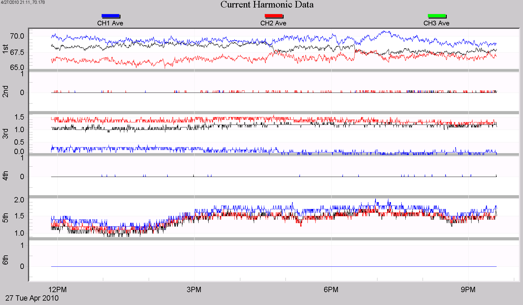
Harmonic stripchart data is displayed in ProVision as interval graphs and 3D plots. In Figure 2, harmonic interval data from 3 channels is plotted – current harmonic magnitudes from 1 through 6. The 1st harmonic (the fundamental) is around 65-70A, while the 3rd and 5th are around 1.5A. The even harmonics are close to zero. Each individual harmonic may be graphed with RMS voltage, current, or any other stripchart trace.
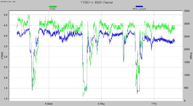
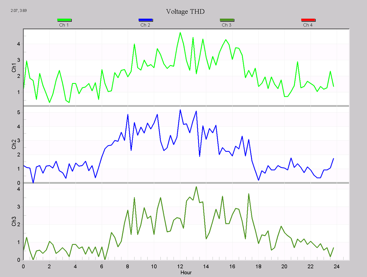
In Figure 3, Voltage THD (green trace) is graphed with RMS current (blue trace). There is a clear correlation here – when the current is high, the voltage THD is high, indicating the load is likely the cause of the voltage THD.
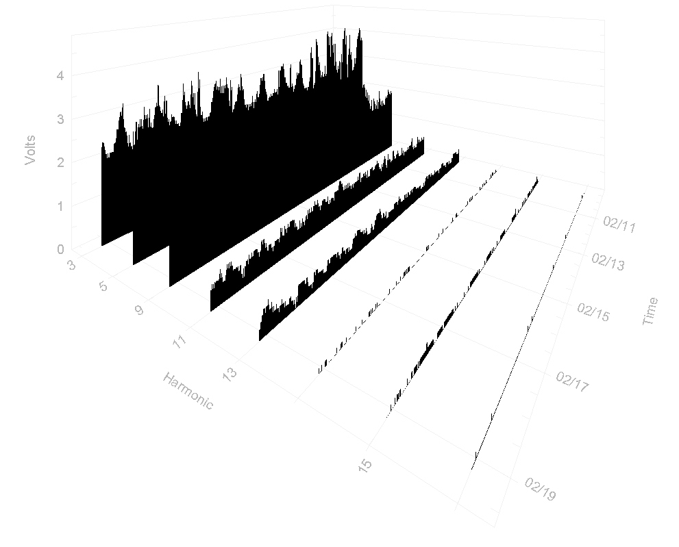
Harmonic interval data may also be graphed in 3D form with ProVision. Figure 4 shows a 3D graph from voltage channel 1, with the odds from 3 through the 17th. These are the average traces from the stripchart data, plotted with harmonic number on the x axis, time on the y axis, and magnitude on the z axis. The 3D plot is very useful for getting a quick view of which specific harmonics warrant further investigation. These can then be graphed individually with 2D stripcharts to show more detail, or to compare with RMS voltage, current, etc.
The entire harmonic trend dataset may be exported from ProVision for analysis in Excel or other data package. This may be useful for regional TDD computation, or to combine with non-PMI data.
Daily Profiles
Daily Profiles are another record type for examining harmonics in ProVision. With these, only voltage and current THD are available – not individual harmonics. In addition, the Daily Profile is an average of the entire recording session, where the “average” 24 hour day is computed. Thus, the information is much less specific than individual trend data for each harmonic, on a small interval. On the plus side, THD Daily Profiles take up very little memory, don’t have any setup parameters, and are always enabled in a PMI recorder that supports harmonics. This makes them easy to use, and always present in a recording even when harmonics weren’t specifically recorded.
Figure 5 shows a voltage THD Daily Profile from a 21 day recording, with THD percent on the y-axis. Here we see that the THD is under 1 or 2% outside of business hours, but climbs to over 4% from 8am to 6pm. This daily trend is more difficult to pick out from a long stripchart. Since these Profiles are always recorded (in any PMI recorder that supports harmonics), it’s a good habit to glance at them even in recordings where harmonics weren’t the primary focus, just in case there may be a problem.
Waveform Capture Analysis
The final harmonic record type in ProVision is the harmonic bar chart, calculated by ProVision from captured waveform data. There is another whitepaper specifically on this (Harmonics from Periodic Waveform Capture Data), but the basics are covered here. ProVision can analyze any captured waveform from a PMI recorder, and perform a harmonic breakdown on any cycle. With this method, all 51 harmonics, magnitude and phase, are always available without using large amounts of memory, since they’re computed by ProVision. In addition, harmonics don’t need to be enabled in advance – any captured waveform may be analyzed. The downside is that harmonic information is only available if/when a waveform was captured. Since most triggered waveforms are due to disturbances, it’s important to choose a “normal” steady-state cycle in a triggered capture – the grey selector window in the ProVision graph may be moved to a good location. Periodic waveform capture is helpful when using this method, to ensure that representative cycles are available through the recording session.
Figure 6 shows the recorder settings page for waveform capture in ProVision. The circled parameters are the most important in using periodic waveform capture for harmonic analysis. The capture period (4 hours here) should be frequent enough to catch differing harmonic levels during the day and night, while not being so frequent that data is overwritten. The samples/cycle may be reduced from 256 to 128 – that’s still enough for ProVision to calculate to the 51st harmonic, and doubles the number of waveforms that will fit into memory. The number of voltage and current channels should be reduced to just those required.
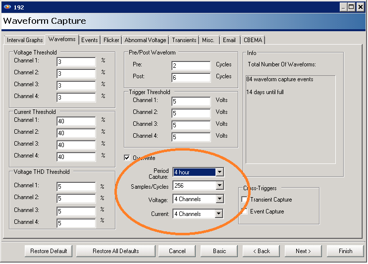
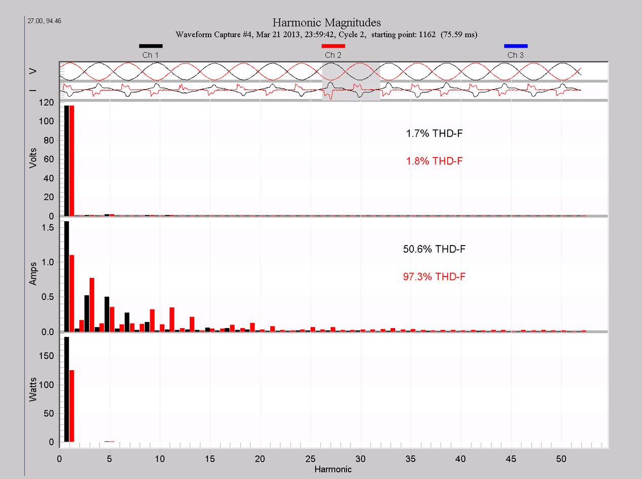
Figure 7 shows a typical harmonic bar chart from waveform capture data. Here a single-phase service was monitored, and the grey cycle window at the top of the graph was moved to a “normal” cycle in the capture. All harmonics from 1 through the 51st are shown (the fundamental may be toggled off to avoid having autoscaling hide the smaller harmonics). In addition, harmonic power is displayed.
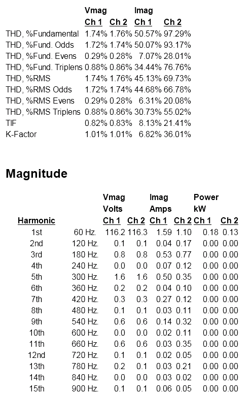
By right-clicking the graph and selecting “Launch Report,” all harmonic values may be viewed in tabular form (Figure 8). Various THD values broken down by evens, odds, triplens, etc. are computed at the top of the display, and magnitude and phase values for voltage, current, and power are given for each harmonic through the 51st.
Recommendations
For an initial PQ recording where harmonics aren’t suspected to be a problem (survey recording, flicker investigations, etc.) at least enable periodic waveform capture, with a period designed to give at least two waveforms per day (e.g. every 12 hours for 1-2 week sessions, or every 1 or 2 days for longer recordings). These waveforms are useful as a baseline for harmonics and other purposes in any case. If memory is tight, or the recording has already taken place, the THD Daily Profiles can be used. If some stripchart memory is available, the voltage and current THD traces should be enabled.
For harmonic investigations, increase the frequency of periodic waveform capture to insure coverage at various points throughout the recording session. Also, enable at least the current harmonic magnitudes, for the fundamental and the odd harmonics up to at least the 11th, or even the 17th. It’s rare to need harmonic data past the 31st, and the higher harmonics can be computed from the periodic waveform capture data, so it’s usually not necessary to record stripchart harmonic data all the way to the 51st. If many harmonics are needed as stripchart data, make sure only the required channels are enabled – e.g. disable channel 4 on a Revolution or Eagle 440 if only using 3 channels. Also, lengthen the stripchart interval to ensure that stripchart data covers the entire recording time. Only record harmonic phase angles if absolutely needed – this information is not often useful, and can also be taken from the periodic waveform capture analysis. Even with full stripchart and waveform capture harmonic data available, don’t disregard the Daily Profiles – the daily trend information can reveal patterns that aren’t obvious with the other views.
