Abstract
This whitepaper is a continuation of WP241 (Recorder Setup Basics). In part one the details and relative memory consumption of interval recording was discussed along with the associated controls for working with the initialization screens. The whitepaper started with the “Basic Screen” and concluded with “Interval Graphs” in the advanced initialization settings. The next item to be covered from the advanced settings is the “Waveform Capture” screen. Waveform capture provides the most detailed information possible – the raw sampled data, but consumes memory more quickly than every other record type. Understanding the waveform capture setup is important in gathering the most useful data possible in a recording.
Waveform Capture
As explained in part 1, the initialization options are accessed by right clicking on a connected recorder in ProVision’s devices window and then selecting “Initialize.” Choosing the “Advanced” option at the bottom of the “Basic Screen” will enter the more detailed area of ProVision’s initialization which includes the waveform capture settings. Select the “Waveforms” tab to go to the “Waveform Capture” screen as shown in Figure 1.
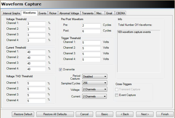
The waveform capture settings are used to set various types of trigger conditions to initiate a snapshot capture of a predetermined number of cycles and channels. The captured waveforms can be downloaded to ProVision as part of a recording and then analyzed in greater detail. The waveform capture screen has six different settings which may be used to trigger a capture event. These settings are all designed to be used together to collectively cover a range of likely disturbances. Note that a triggered event on any channel will result in a capture of all enabled channels.
- Voltage Threshold: The voltage threshold is expressed as a percentage value. It defines the percentage of RMS voltage variance that will trigger a waveform capture as measured from cycle to cycle. A separate percentage value may be specified for each channel on the recorder. If a percentage value is set to zero then the percentage check will be skipped for the associated channel.
- Current Threshold: The current threshold is expressed as a percentage of the maximum current of the programmed current range. The calculated value is the change in current that will trigger a waveform capture as measured from cycle to cycle. As with the voltage threshold, a separate value may be specified for each channel and if set to zero then the check will be skipped for the associated channel.
- Voltage THD Threshold: The voltage THD threshold is expressed as a percentage value. However, THD (total harmonic distortion) is itself a ratio specified as a percentage. The value entered here is the absolute THD change from cycle to cycle that will trigger a waveform capture. It has the same per channel settings behavior as the voltage and current thresholds.
- Trigger Threshold: The trigger threshold is specified in volts and represents the absolute RMS voltage change from cycle to cycle that will trigger a waveform capture. Once again, the per channel settings apply.
- Cross Triggers: The cross triggers are not dependent on a defined waveform change as the previous triggers. Instead, it is a checkbox field that allows for a waveform capture to be triggered based on other types of system measurements that may benefit from seeing the associated waveforms. The “Transient Capture” (if supported on the recorder) or “Event Capture” cross triggers are used to initiate a waveform capture when either of these other measurements trigger on their respective monitoring parameters.
- Period Capture: The period capture is pretty much self-explanatory. A waveform capture will be initiated periodically based on the selected time base value. The time base is selectable via a pull down menu and ranges from 1 minute to 4 weeks. Periodic “normal” waveforms are very helpful to establish a baseline distortion, and for harmonic analysis in ProVision without recording harmonic stripcharts.
The thresholds and other settings just mentioned define when or under what conditions a waveform capture will occur. The other areas of the “Waveform Capture” screen contain various control and information fields related to what, how and how much is captured. Monitor the info field (Total Number Of Waveforms) as the following items are entered to see how each affects the available storage.
- Pre/Post Waveform: This field specifies the total number of cycles to be captured per event per enabled channel. The total number of cycles is broken down into pre-cycles (number of cycles preceding the trigger event) and post-cycles (number of cycles following the event). This mechanism allows a triggered event to be captured in context. There are no hard limits to the number of pre or post cycles but there are practical limits based on the internal capture and storage capacity of the recorder (varies by recorder model). For the Revolution, Guardian, and Eagle, recording times over 10 seconds (600 cycles) are possible in single captures. Long captures are useful for motor start studies and monitoring load or line changes that have lengthy settling times.
- Samples/Cycles: The number of samples per cycle may be modified here. The setting utilizes a pull down menu with 5 available settings from 256 down to 16 samples per cycle. Reducing the number of samples per cycle greatly increases the number of events that can be captured but reduces the usefulness of the captured data. The details and tradeoffs involved when changing the samples per cycle are explained in WP-248 (Adjusting Waveform Capture Sampling Rates). It’s recommended to choose at least 128 samples per cycle for harmonic studies or high resolution oscillatory transient analysis, and only use lower resolutions as needed for AC motor starts and other non-distorted waveforms.
- Voltage Channels: This field specifies the number of voltage channels to be monitored and used for capturing events. The setting uses a pull down menu to select “None” up to the available number of channels in the recorder. The voltage and current channels used for waveform capture are selectable here independently of the values used for stripchart recording.
- Current Channels: The current channels are specified in the same way as the voltage channels.
- Total Number Of Waveforms: Waveform captures are saved in a dedicated storage area in the recorder. The size of each waveform capture event is calculated based on the pre/post cycles, samples per cycle and number of channels. This allows the total number of capture events to be calculated immediately (based on selected settings) and the number is shown in this field.
- Overwrite: This is a simple checkbox that specifies what should happen when the waveform capture memory is filled to capacity. If enabled then the oldest capture event will be overwritten with any new event. If disabled then waveform capturing stops.
The controls at the bottom of the “Waveform Capture” screen are the same for all advanced programming screens and were covered in detail in part 1 of this series.
Availability
Most of PMI’s recorders support waveform capture but some do not contain all of the above mentioned settings. The availability of settings for each recorder type is shown in Table 1.
| Recorder | Voltage Threshold | Current Threshold | vTHD Threshold | Trigger Threshold | Period Capture | Cross Triggers |
|---|---|---|---|---|---|---|
| Revolution | Yes | Yes | Yes | Yes | Yes | Yes |
| Guardian | Yes | Yes | Yes | Yes | Yes | Yes |
| Eagle, Eagle 120 | Yes | Yes | No | Yes | Yes | No |
| iVS-2SX+ | Yes | No | No | No | No | No |
Conclusion
Waveform capture is an important data type when investigating power quality issues. It can show the cycle level detail of a line disturbance if the settings are properly chosen to trigger on an associated condition. The settings used for waveform capture allow for various types of triggers and volume of data to be captured. The use of cross triggers to tie waveform capture to other monitored conditions further extends the usefulness of this powerful feature.
