Abstract
This white paper describes the proper ProVision settings for wired communications with PMI Recorders.
PMI offers many different communication options to satisfy the needs of the industry. With many power quality analyzers to choose from, the communication settings differ within ProVision software. The older style recorders such as the IVS, VIP, and Stray Voltage monitor use the Serial or RS232 protocol for communications with the PC.
Newer models like the Revolution, Vision, Eagle, and Guardian offer more complex communications such as USB, Bluetooth, and Ethernet. In order to take full advantage of these communication standards it is necessary to setup ProVision software to fully comply with these devices.
Serial Communications
As previously mentioned, legacy products use serial communications to interact with PQ software. Serial devices require the use of an external power supply to run the circuitry needed for this type of communication. It is very important to first power the unit with the provided external power supply before trying to connect serial PMI devices. After the unit is powered up, open Provision and follow the few steps listed below.
-
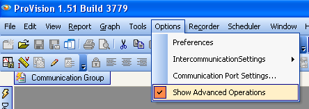
Advanced Operations. Under Options make sure the Show Advanced Operations is Checked and shown in Figure 1, above.
-
Recorder Communication Settings. Under Options Click Communications Port Settings and the Dialog box will appear as shown in Figure 2:
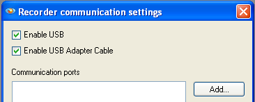
Figure 2. Recorder communication settings main screen -
Add Connection. Click Add and then Select Serial as shown in Figure 3:
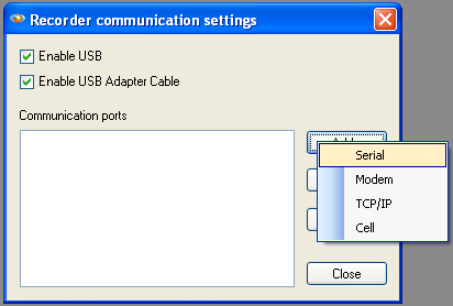
Figure 3. Add serial connection -
Connection Properties. After the Serial Link is added the Connection Properties Dialog box will appear as shown in Figure 4:
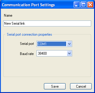
Figure 4. Connection properties -
Name. In the name window create a custom name for the serial link to the recorder.
TIP: Choose a name for the specific Recorder you are using and add the serial number to identify the exact unit. Example: VIP – Serial 31035 as shown in Figure 5:
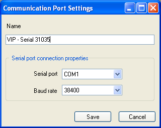
Figure 5. Connection properties example -
Serial Port. Choose the serial port that will be used on the computer. NOTE: Most computers only have one serial port and are identified as COM1.
-
Baud Rate. The baud rate is the speed at which the serial port transfers data to and from the connected device. This can be altered to speed up or slow down the data transfer with the PMI recorder but it is recommended to be set at 38400.
NOTE: ProVision will scan through the baud rates and try to establish a stable connection automatically.
-
Save. After all parameters are set in the connection properties dialog Click Save.
-
Communication Ports. After successfully creating a new serial connection the port will appear as shown in Figure 6:
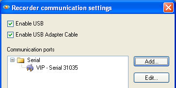
Figure 6. Ports -
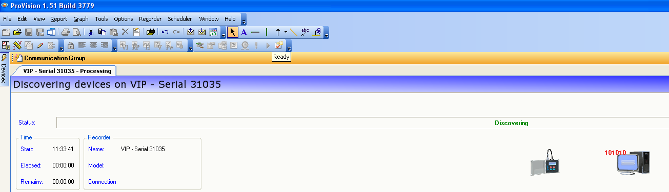
Connecting to a Recorder. After connecting the serial port and power cables Click Recorder > Connect and select the New Serial connection. ProVision will scan for the connected Recorder on COM1 and connect as shown in Figure 7, below.
-
After the connection is made it will be possible to interact with the Recorder.
USB Communications
USB communications are offered on our new product line as mentioned previously. PMI USB Devices power themselves from the USB port thus no external power supply is needed. USB connections are automatically detected within ProVision and there is no connection requirement to be made. The only requirement for USB communication is the driver must first be installed on the host computer. Follow the steps below for USB communication with PMI Recorders.
-
PMI USB Driver Install. This driver is free and can be downloaded via www.powermonitors.com/download. After downloading the file from the website, run the setup file and follow steps provided with the software.
-
Plug-in the USB cable. After the driver is loaded, plug-in the USB port on the PMI recorder and wait for the Windows “New Device Wizard” to start. Windows will automatically search for the previously installed drivers and successfully register the device on the PC.
-
Communication. The USB device is automatically detected within ProVision and will show up in the device window as shown in Figure 8.
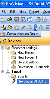
Figure 8. Automatic USB detection -
After ProVision detects the USB device it will be possible to interact with the Recorder.
NOTE: It is not possible to connect multiple USB devices to ProVision at one time; make sure that the correct device is chosen in the devices window before trying to interact with it.
Ethernet Communications
Ethernet communication is offered only on Revolution and Vision power quality analyzers. Ethernet devices offer the ability to connect over a much longer distance than USB and serial connections. Ethernet is commonly used when the recorders are permanently installed and need to be accessed globally. In order to use Ethernet communications the recorder must be powered by AC voltage on Channel 1. After the unit is powered up, connect to the Ethernet network, open Provision and follow the steps below.
-
Obtain IP Address. If the IP address of the Revolution/Vision Recorder is known then skip the SNET steps below. In order to connect the Revolution/Vision to the Provision Software it is necessary to first obtain the IP address of the Revolution on the Ethernet Network. To simplify the process PMI offers a SNET utility that can be found at www.powermonitors.com/download
-
SNET. Run the SNET.exe utility and Click TCP Find; this will locate any Revolutions/Visions on the local Ethernet Network and report the serial number and IP address of each identified recorder as shown in Figure 9:
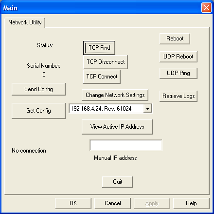
Figure 9. TCP Find -
IP Address. Take note of the IP address of the discovered recorder because this will be needed later. Close the SNET utility and proceed to the steps below to set up the ProVision software.
-
Advanced Operations. Under Options make sure Show Advanced Operations is checked as shown in Figure 10, above.
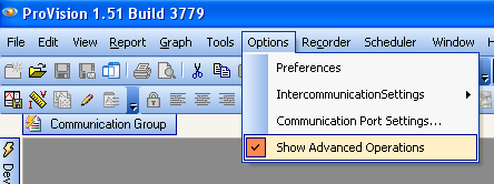
Figure 10. Advanced operations -
Recorder Communication Settings. Under Options Click Communications Port Settings a dialog box will appear as shown in Figure 11, below.
-
Add Connection. Click Add and then Select TCP/IP as shown in Figure 12, below.
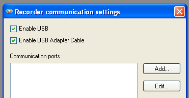
Figure 11. Recorder communication settings main screen 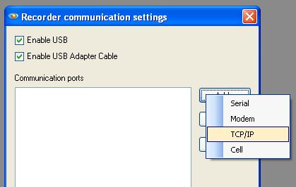
Figure 12. Add TCP Connection -
Connection Properties. After the TCP Link is added the Connection Properties Dialog box will appear as shown in Figure 13.
-
Name. In the name window create a custom name for the TCP Link to the recorder. Hints: Choose a name for the specific Recorder being used and add the serial number to identify the exact unit. Example: TCP Revolution Link 61024 as shown in Figure 14.
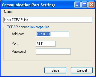
Figure 13. Connection properties 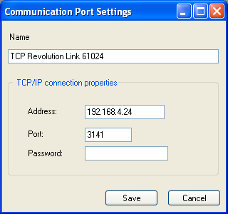
Figure 14. Connection properties example -
Address. The IP address of the connected device needs to go here. This is the result of the SNET utility TCP find function as shown in Figure 9.
-
Port. The port is the TCP port that the Revolution uses to connect. This defaults to 3141 and should not be changed.
-
Password. The password is a feature that will be added at a later date and is not necessary at this time.
-
Save. After all parameters are set in the connection properties dialog click Save.
-
Communication Ports. After successfully creating a new TCP connection the Port will appear as shown in Figure 15, above.
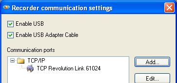
Figure 15. Ports -
Connecting to a Recorder. After connecting the Ethernet port and powering the Revolution/Vision via AC voltage on CH1, Click Recorder > Connect and select the New TCP connection. ProVision will scan for the connected Recorder on the TCP port and connect as shown in Figure 16, above. After the connection is complete it will be possible to interact with the Recorder.
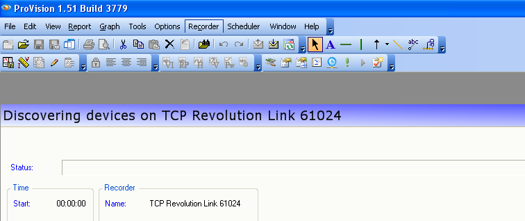
Figure 16. Scanning for the recorder
Conclusion
With a little background knowledge on communications settings used to connect a PMI power analyzer, it will be possible to spend more time analyzing data and less time trying to retrieve it. Review of the software interface and connection properties is a time well spent.
