Abstract
ProVision’s native data file format is designed for efficient storage and access of all PQ data from the full line of PMI recorders. However, ProVision can also export certain data types into IEEE 1159.3-compliant PQDIF format. Exported data includes all interval, waveform capture, and aggregated sliding-window RMS capture data. The details of ProVision’s PQDIF export data types, options, and export mechanisms are reviewed here.
PQDIF
PQDIF (Power Quality Data Interchange Format) is a binary file format for storing power quality data. Originally a custom, proprietary format, it has been placed in the public domain, and has been standardized in IEEE Std. 1159.3. Although PQDIF is not the native format of any PQ equipment vendor, many software and power analyzer vendors support export to PQDIF format, for vendor-independent data analysis and archiving. In addition, several software vendors offer electrical simulation tools which import PQDIF data. In many cases, PQDIF is used in place of the older IEEE COMTRADE file format.
With ProVision, any recorded data file (XSF or XSB) may be exported to PQDIF format. This export always takes a single ProVision data file, and creates a PQDIF export file containing only data from original recording session. Multiple ProVision files may be exported, but each individual file will result in a corresponding PQDIF file.
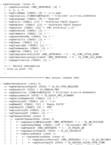
A PQDIF data file consists of a hierarchical set of records. The top-most record is a “Container”. In the ProVision export, this container record holds the data set from the original file. Inside the top-most container is a Data Source record – this single record represents the PMI PQ monitor used to record the data session. Information such as device type, serial number, etc. are stored in the Data Source record. The detailed PQDIF format calls for a complex set of nested records – a partial view is shown in Figure 1, from a deconstructed PQDIF export.
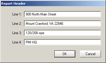
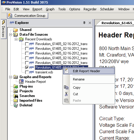
One option for the Data Source record is the PQDIF Data Source Name. This parameter is used as a site location name in some 3rd party software. The “Data Source Name” option in the PQDIF Setup screen gives three options for what’s exported to this PQDIF tag. The default is the PMI recorder name, e.g. “Revolution nnnn”, where nnnn is the device serial number. The original ProVision file name may also be selected, which, if generated automatically from a scheduled download, will consist of the Recorder name and serial number, plus the date of the download. The last option is the “Header Line Four”, which is the fourth line of the Report Header in the original data file. Each PMI data file includes a four line text header (Figure 2), which can be used to enter the street address, notes about the recording, etc. If “Header Line Four” is chosen, then whatever text is contained in the fourth header line is used for the Data Source Name. If a specific location name or street address is needed in the PQDIF export, then this should be entered in line four of the header, and exported with this option. To edit a report header, open a ProVision file, then right-click on the file in the Explorer panel, and select “Edit Report Header” (Figure 3).
In addition, Channel Definition records are also stored in the Data Source record. These records contain information about the voltage and current channels used in the original recording.
The PQDIF format includes support for periodic and triggered measurements. In ProVision, these correspond to interval (stripchart) and waveform capture data. These records are stored as Observation Records in the PQDIF output.
In a PMI recorder, an interval data record is a collection of min/ave/max measurements, collected on a periodic basis (e.g. once per minute), spanning all enabled data types – voltage, current, power, etc. When a recording is paused, or interrupted due to an outage or loss of battery power, the currently running interval record is ended. When the recording resumes, a new interval record is begun. A recording session may only include a single interval record, if the entire recording was uninterrupted by an outage or user pause. Multiple power outages that last longer than the ride-thru battery time will result in multiple interval records in a single recording.
These individual interval records map directly to PQDIF Observations in the export format. Each interval Observation has a start time, length, recording interval, and data type definitions. The latter two items will be the same for all the observations in a single PQDIF export, but the start time and length will be different for each Observation. An Observation will include all interval data during that time span. For example, if a Revolution were configured to record voltage, current, real power, voltage THD, and Pst Flicker, then each of those data types, for all channels, including min/ave/max readings for each interval will be stored in an Observation. Within an Observation, multiple Series Instances are used to record each interval trace – e.g. RMS voltage, min, channel 1 will be stored in a single Series Instance, within a specific Observation.
All interval data is exported into PQDIF format. This includes the basic quantities such as RMS voltage, RMS current, real, reactive, and apparent power, power factor, and displacement power factor. For harmonics, both magnitude and phase information for all recorded harmonics, and also voltage and current THD are exported. The magnitudes are in absolute units (e.g. Volts or Amps, not percent of fundamental or RMS), and the phases are in degrees. Finally, frequency, in Hertz, and Pst, Plt, and IFL flicker are exported, measured and scaled as per IEEE 1453. If voltage or current scale factors were originally stored in the ProVision file, all exported interval data is scaled using those factors.
Specialized, PMI-specific stripcharts in ProVision, such as the Significant Change Reference, or the Power Demand or Total Power interval graphs, are not exported to PQDIF. There are no settings to adjust for PQDIF export of interval data. Only the interval originally in the source file may be exported into PQDIF.
Waveform capture data is the second fundamental data type exported into PQDIF format from ProVision. Like the interval data, triggered waveform capture records are exported as PQDIF Observation records, with a separate timestamp and data length, and a Data Series instance for each recorded channel. Instead of min/ave/max data, the waveform export consists of instantaneous voltage and current samples. These samples are the same as displayed in ProVision in the waveform graphs.
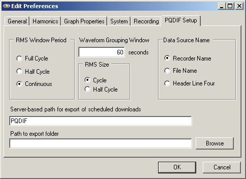
There is one important difference for the Observation records in waveform capture, vs. interval data. For waveform capture, if multiple waveforms are triggered within a certain (configurable) timespan, these separate captures are all exported within the same Observation Record. The intent here is that if the captures are close in time, the root source of the captures is likely a single, complex event, and should be grouped together. For example, a long, complex sag waveform could trigger two or more waveform captures, one for the sag, and one for the return to nominal voltage. If these are closely spaced, then they are combined as one “event” in an Observation record, even if there is a gap between the two individual waveform captures. Some 3rd party data analysis tools produce statistics based on the number of Observation records, assuming each record is a single event, and this automatic grouping is important in the getting valid statistics. This setting is the Waveform Grouping Window in the PQDIF Setup screen (see Figure 4), and defaults to 60 seconds. A value of zero will disable aggregation of waveform captures.
The trigger source for waveform capture is also exported. Waveform captures that were triggered from a voltage or current threshold are marked as triggered, and waveform captures from a periodic capture are marked as periodic in the PQDIF export. This tagging is important in certain 3rd party statistical counts, where triggered events are tallied. In addition, an automatic harmonic analysis can be performed in some PQDIF analysis tools, and this should only be done on periodic waveform captures (to compute harmonics from “normal” steady-state waveforms).
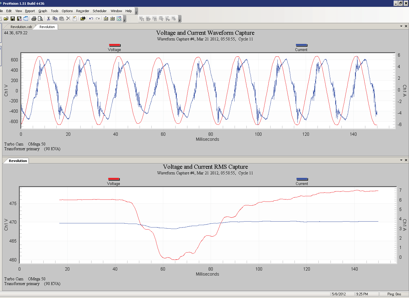
In addition to instantaneous waveform data, a second data type is computed by ProVision and exported to PQDIF – RMS Variation. The RMS Variation is a sliding-window RMS calculation computed from the instantaneous waveform capture data. With the default settings, a full-cycle RMS value is computed and exported, for the first cycle’s worth of waveform capture data. Then, the cycle RMS window is moved one sample (e.g. 65 microseconds with normal settings), and a new RMS value is computed. This window slides one sample at a time, and results in a continuous RMS waveform, with the same sampling rate as the original waveform data (but overall one cycle shorter in length). See Figure 5 for a triggered waveform capture, and the corresponding RMS sliding window output (available as graph in ProVision from Graph, Waveform Capture, RMS Capture).
The RMS computation may be done on a full cycle, or half cycle window. The “RMS Size” setting is used to select this. In addition, the sliding window can slide by a single waveform capture sample, or in whole half or cycle jumps. The RMS Window Period controls the window sliding parameter, with Continuous meaning the window moves by one waveform capture sample at a time. If this is set to Full Cycle or Half Cycle, the resulting RMS Variation will only have a few data points – one per cycle or half cycle of the original waveform.
The RMS Variation Observations are combined in the same fashion as the Waveform data, grouped according to the “Waveform Grouping Window” setting.
Although the PQDIF format specifies methods for several different data types, the generic vendor-independent nature of the format precludes support for specialized record types. These include ProVision data types such as Significant Change, Event Capture, Abnormal Voltage and Loose Neutral, etc. Also the Daily Profile and Histogram data are not exported to PQDIF.
To export a file to PQDIF, the original data file must be in the Projects node of the Explorer panel. If it’s not there, drag the file from the Data File Sources section into the Projects node. Right click on the file, and choose “Export to PQDIF” (see Figure 6). A dialog box will appear, prompting for a destination folder, and file name. The name will default to the original file name, but with the .pqd file extension.
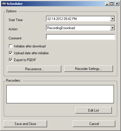
The second method to export into PQDIF format is automatically, from a scheduled download. If ProVision, or the background ProVision Communicator Service, is configured to automatically download PMI recorders, the output is saved in the ProVision native format. The scheduler can be configured to also export and save a copy in PQDIF format (see Figure 7). During the scheduled file save, the path listed in the “Server-based path for export of scheduled downloads” is used as the destination path for all PQDIF exports. The other PQDIF export options are also obeyed. The file name is identical to the ProVision file name, but with the .pqd file extension.
The ProVision PQDIF export allows manual or automatic creation of PQDIF data from PMI recorders. In addition to standard interval and waveform capture data, RMS Variation calculation and configurable aggregate waveform grouping creates PQDIF data ready for analysis in any 3rd party PQDIF data tool.
Links for Further Reading
IEEE P1159.3 on-line documents:
http://grouper.ieee.org/groups/1159/3/docs.html
