Abstract
In this white paper I review K-factor in regards to power transformers, how K-factor is defined and calculated and how K-factor is used. K-factor is a way of rating or de-rating a transformer’s handling capacity in the presence of a non-linear load, with the goal of preventing transformer overheating. The normal range of the K-factor is from 1 to 50. A K-Factor of 1 indicates a purely linear load with no harmonics, while a K-factor of 50 would indicate a severely non-linear load very rich in harmonics. The higher the K-factor rating on a transformer, the larger the nonlinear load it is designed to handle without overheating. Heat is one of a transformer’s largest enemies and can lead to a reduction in its lifespan, or even failure.
An Introduction to K-Factor
As technology has grown, it has continuously introduced more nonlinear loads (such as switching power supplies, variable frequency drives, etc.) to the electric distribution system, which in turn creates larger harmonic problems. As more harmonics are introduced due to these nonlinear loads, they will cause transformers to heat up at a much faster rate than a more linear load previously would have. The heating in the transformer can be attributed to several sources. One heat source comes from additional losses beyond the normal I2R type. These losses are due to the skin effect associated with the higher frequency components of the harmonics. Triplen harmonics can cause additional currents to flow in the neutral conductor, which in turn cause heating. In larger K factor transformers the neutral conductor is increased in order to handle the increased currents, and surface area thus reducing its overall impedance. There are various other losses in the transformer that cause heating, but the majority is due to eddy currents. The transformer’s eddy current losses are proportional to the harmonic current squared times the harmonic number squared. As the transformer begins to heat up, the resistance in the windings will also increase slightly due to the temperature coefficient of copper, which can compound the heat problem.
The major cause of transformer failure is a breakdown in the transformer’s insulation. Heat has an adverse affect on the transformer’s insulation, and the proper sizing of the transformer with the load and the load’s harmonic content is very important to ensure the transformer will have the intended 20 to 30 year lifespan. Experiencing a short-lived increase in power will increase the transformer’s heating, however if the power surge is not too long, the transformer’s temperature will not rise to the point of damaging the insulation due to the transformer’s large thermal mass. Running a transformer at a higher than stated nameplate capacity may work for a while; however it is a recipe for a premature transformer failure and should be avoided. Transformers are certainly not inexpensive, and there is a relationship between the size and the cost of the transformer. It is sometimes a little challenging to make sure the transformer has enough capacity to take care of the peak power demands without having to over spend for transformer capacity that is not needed. K-factor makes this task a little easier. K-factor transformers were specially designed to handle the loads with higher harmonic current content. They have additional thermal headroom to handle the additional heating within specific parameters allowing them to operation with sufficient capacity without the need for de-rating their name plate specs.
The K-factor indicates the amount of de-rating a specific transformer has for handling a specific amount of load nonlinearity. The higher the K-factor, the greater the expected load nonlinearity becomes, and the more harmonics the particular transformer can tolerate without overheating. It is important to make measurements to evaluate the magnitude of the transformer’s load nonlinearities in order to make sure the correct K-Factor rated transformer is being used for a specific load.
K-Factor can be derived by the following equation:
where h = harmonic number, Ih = the fraction of the total RMS load current at the harmonic h, and hmax = the highest significant harmonic number.
It is important to remember that the K-factor is a weighting of the harmonic load currents according to their effects on transformer heating, as derived from ANSI/IEEE C57.110.
As seen in the above equation, the value of the K-factor is affected much more by the higher harmonics than by the lower ones. In fact the eddy current losses (thus the K factor) are proportional to the harmonic currents squared times the harmonics number squared. For example, consider 1 amp of current at 60 Hz, and the amount of heating it produces on a given transformer. If that 1 amp were at the 3rd harmonic (180 Hz), the heating effect is 3×3 = 9 times higher than at 60 Hz. For the 5th harmonic, the heating effect is 5×5 = 25 times higher. These are extreme examples; in a real situation there will be some 60 Hz current to mitigate the effect. For example, a transformer with 100A at 60 Hz, 40A of 3rd harmonic, and 20A of 5th harmonic will have an RMS value around 110A (the harmonics generally RMS add). The K-factor would be (100/110) + (40/110)x3x3 + (20/110)x5x5 = 0.91 + 3.27 + 4.54, or 8.7 total. The 5th harmonic contributes more than the 3rd, even though it’s only half the magnitude of the 3rd.
A K-factor of 1.0 indicates a linear load at 60 Hz with no harmonics. The higher the K-factor, the greater the harmonic heating effects.
IEEE Recommendations
There are guidelines put into place by the IEEE governing K-factor. If the load is relatively linear with harmonic currents of less than 15% THD-I, (the current’s total harmonic distortion) it is permissible to use a non-K rated transformer. For loads of anything even slightly greater than 15% to 35% THD-I, a K-4 rated transformer should be used. Loads from 35% to 75% THD-I, a K-13 transformer is needed and for loads with a harmonic current content of 75% THD-I and above, a K-20 transformer need to be installed.
Below is a list of typical loads and the typical K-Factor rating for their expected non-linearity:
K-Factor levels:
- K-1 Standard transformers for standard lightning and motors
- K-2 Induction heat, SCR, AC Drives
- K-4 Electrical Discharge Lights, UPS w/option input filters, welders, inductive heating, PLC and solid state controls
- K-13 School pulse lightning and hospital use
- K-20 Data processing computer, computer rooms
- K-30 Multi-wiring receptacles circuits in Commercial office space and small main frame computers
- K-40 Loads producing very high amounts of harmonics
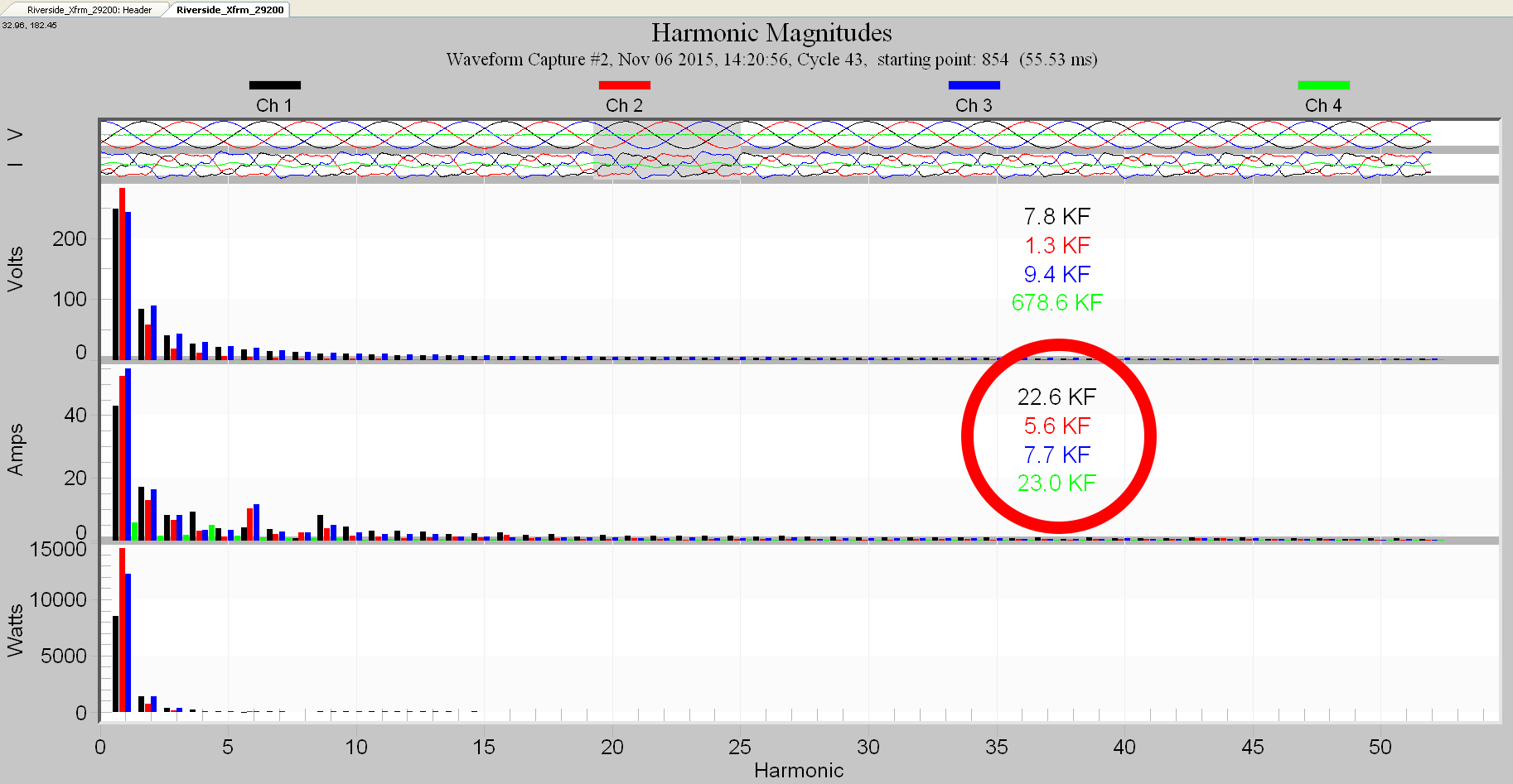
Using ProVision to Analyze the K-Factor
Provision is a great tool for aiding and determining the current’s harmonic content generated by a specific load, which is directly related to the K-factor. To do this you must first make a recording of the load in question with one of the PMI’s many recorders. You will need to perform both current and voltage measurements, since the K-Factor is derived from the current waveform and requires phase information. Then in Provision load the waveform capture file. At this point you can simple click on the harmonic toolbar icon to switch to analyze the harmonic waveform. There are other ways to do this, such as go directly to the same place with Graph, Harmonic Analysis and then to Magnitudes on the toolbar. Now you should be at the same place either way so now select a waveform capture record. At this point you should see THD visibly displayed on the graph. Now simply click on the graph annotation and it will switch to show K-Factor for the displayed waveforms. At this point, to select the cycle that is to be computed, move the gray cycle box in the top trace to select the cycle, as shown in Figure 1. It is important to remember that PMI recorders do not actually compute the K-Factor as such, it is rather a calculation performed on the individual waveform capture. Because of this, it is important to pick a cycle that is more the norm, and not one that is in, or close to a disturbance, such as a random capacitor bank switch, for example. Since the K-factor reflects the transformer’s heating phenomena, and with the huge thermal mass of a power transformer, this relates to a more steady state reading and not an infrequent anomaly. This will provide a more meaningful K-factor value.
Conclusion
It is important to have systems in place to monitor and analyze the power quality issues that can affect critical and expensive components in a power distribution system. As new technologies are constantly being introduced in the power distribution system that create large non-linear loads, it is wise to keep a close eye on loads and have them re-checked regularly to make sure they are within proper operational parameters of the existing transformer’s K-factor. As demonstrated in this paper, it only takes a couple of simple steps and very little time using Provision to verify the harmonic content and load on a transformer.
