Abstract
PMI recorders are capable of storing a large amount of data. The recording setup stored in the device determines the data that will be captured during a recording session as well as the maximum duration of the recording. Each PMI recorder has a default setup that may be customized to capture specific types of data that are deemed by the user as important for the current investigation. Customizing the setup also allows for extending the potential duration of the recording by limiting or disabling unnecessary data. This whitepaper will explore the basic initialization settings plus those that are used to control the interval data capture. A future whitepaper will pick up where this one ends and continue with other parts of the initialization menus.
Overview
Power quality issues are often resolved by capturing the right data at the right time in the correct context and sometimes with the correct detail. Initializing a recorder with the correct mix of data to be captured, thresholds to trigger on, time intervals to utilize, number of channels and numerous other available options gives tremendous flexibility in tracking down power quality issues. Since the storage capacity of PMI recorders is large but finite, capturing large amounts of data in detail cannot be accommodated for very long. The default settings of PMI recorders are designed to catch a broad spectrum of general information over a long period of time that will hopefully expose clues as to the specific data needed to solve a power quality problem.
Basic Initialization
PMI’s ProVision software is used to initialize a recording. Once connected to the device simply right click on the connected device’s name and choose “Initialize.” If the device’s existing parameters are to be modified then choose “Retrieve Settings” and then “View” once the settings have been loaded. The “Basic Screen” is now being shown (see Figure 1). It is used to change a few simple, high level items to be used for the recording.
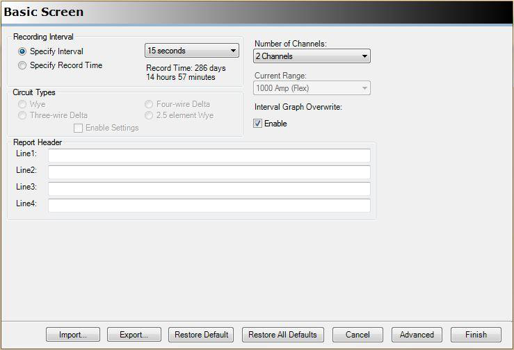
- Recording Interval: This defines the time base for the sampled data stored for the various stripcharts that are currently selected (described in detail in the next section). The recording interval has two modes of input. Both specify the duration of the recording but from different perspectives. Choose “Specify Interval” in order to select the time base used for stripchart recording. The time base is chosen from a pull down menu ranging from 1 second to 4 hours. This is how often the device will record a point of data which is always based on 1 second values. Choosing an interval greater than 1 second will average the 1 second values over the specified interval. The total recording time will be computed automatically. Choose “Specify Record Time” to select the desired time of the entire recording. The recording time is chosen from a pull down menu ranging from 10 minutes to 1 year. The interval required to record for the desired length of time will be computed automatically.
- Interval Graph Overwrite: This checkbox is related to the recording interval selection. When enabled, the device will overwrite the oldest recording data once the device storage capacity has been reached. If not enabled then the device will stop saving the data that pertains to interval recordings while still monitoring all other items specified for this device.
- Number of Channels: This pull down menu selects how many channels are to be used for recording the interval data. It ranges from 1 to the number of channels supported by the device being used. Note that this does not select which channels, only the number of channels starting with channel 1.
- Circuit Type: This is used to describe the circuit being monitored. The circuit type is important for some of the calculations related to data sampling and collection. This field will be unavailable if the device is specific to a single circuit type.
- Current Range: This pull down menu selects the anticipated range of current when the device has current monitoring clamps attached so that proper scaling of the data can be done. The pull down menu selections are specific to the various types of PMI current clamps and range from 20 amps to 5000 amps. This current range will be unavailable if the device has permanent current monitoring capability built in and therefore a known fixed range.
- Report Header: The text based report header lines are used to enter a title, notes, description or other descriptive information about this recording. The text entered here will be shown in the report header generated by ProVision once a recording has been downloaded.
The bottom of the basic screen has multiple controls pertaining to the initialization process.
- Import: Load a set of initialization values from a file.
- Export: Save the current initialization settings to a file.
- Restore Default: Change the basic screen settings to their default values.
- Restore All Defaults: Change all initialization settings (including those in the advanced section) to their default values.
- Cancel: Exit initialization without making any changes
- Advanced: Enter the advanced initialization screens
- Finish: Initialize the device with the current settings
Advanced Initialization
Choosing the “Advanced” option at the bottom of the basic screen will enter the more detailed area of ProVision’s initialization screens. This area consists of multiple screens that are accessed via tabs or by stepping through them with the next and back controls. The first of the advanced screens is the “Interval Graphs” as shown in Figure 2.
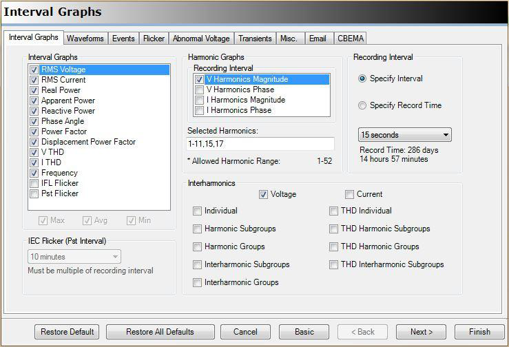
The interval graphs are comprised of a number of different collections of data that will be sampled over time and ultimately displayed as stripcharts or in the case of harmonics as a 3D graph of points over time per harmonic value specified.
- Recording Interval: This is the same setting as described in the basic screen operation.
- Interval Graphs: This is where the actual graph selection is made. Each selection specifies a specific type of data to be recorded. This data will be recorded for all channels specified on the basic screen. These graphs will also be collecting a minimum value, maximum value and average value over the interval specified. Each selected graph contributes directly to the available recording time so it is important to only choose the graphs deemed necessary versus just selecting all. If the desired graphs are checked and the recording time is smaller than required then the recording interval can be increased.
- Harmonic Graphs: This area selects which components of the harmonics are to be recorded. The selections made here in conjunction with the selected harmonics will greatly influence the total recording time since each will cause a graph per selected harmonic per channel to be generated.
- Selected Harmonics: This area utilizes text input to specify the specific harmonics that are to be captured per enabled harmonic graph. The harmonic values may be specified individually (1,3,5, etc) or as a range (1-5, 11-15, etc) or a combination of the two.
- Interharmonics: If at least one harmonic graph has been enabled the associated interharmonics may be specified. These may be selected for voltage and/or current plus any combination of the various types of interharmonic groups and subgroups. These also will greatly reduce the recording time so they should be selected with care.
- IEC Flicker (Pst Interval): The IEC flicker standard uses a standardized 10 minute observational interval which is the default for a recording. This is used to determine the short term flicker “perceptibility” Pst value. Changing this pull down value does not impact total recording duration.
The bottom of the advanced screen has multiple controls pertaining to the initialization process. Some of these are duplicates of the basic screen controls.
- Restore Default: Change the interval graphs screen settings to their default values.
- Restore All Defaults: Change all initialization settings (including those in other tabs) to their default values.
- Cancel: Exit initialization without making any changes
- Basic: Return to the basic screen
- Back / Next: Move backward or forward through the tabs of the advanced settings
- Finish: Initialize the device with the current settings
Conclusion
This has been an overview of the various settings pertaining to interval recording and their effect on the recording duration. The interval graphs are the most often modified initialization parameters and comprise the bulk of the storage in a PMI recorder. Carefully choosing the data being recorded and maximizing the duration of recording is often the key to capturing the information needed to solve power quality issues. Watch for future whitepapers that continue on with other advanced initialization parameters of PMI recorders.
