Abstract
The first electric traffic signals were installed over 100 years ago but now are a ubiquitous aspect of modern life. Today’s intersections are far more complex, with a cabinet of equipment controlling LED signals, video cameras, inductive and radar-based sensors, preemption devices for emergency vehicles, backup power supplies, and high-speed communications. Power quality delivered to and inside these modern cabinets is increasingly important. Troubleshooting a traffic signal problem to a root PQ cause and solution requires a good working relationship between the electric utility and traffic agency.
Cabinet Architecture
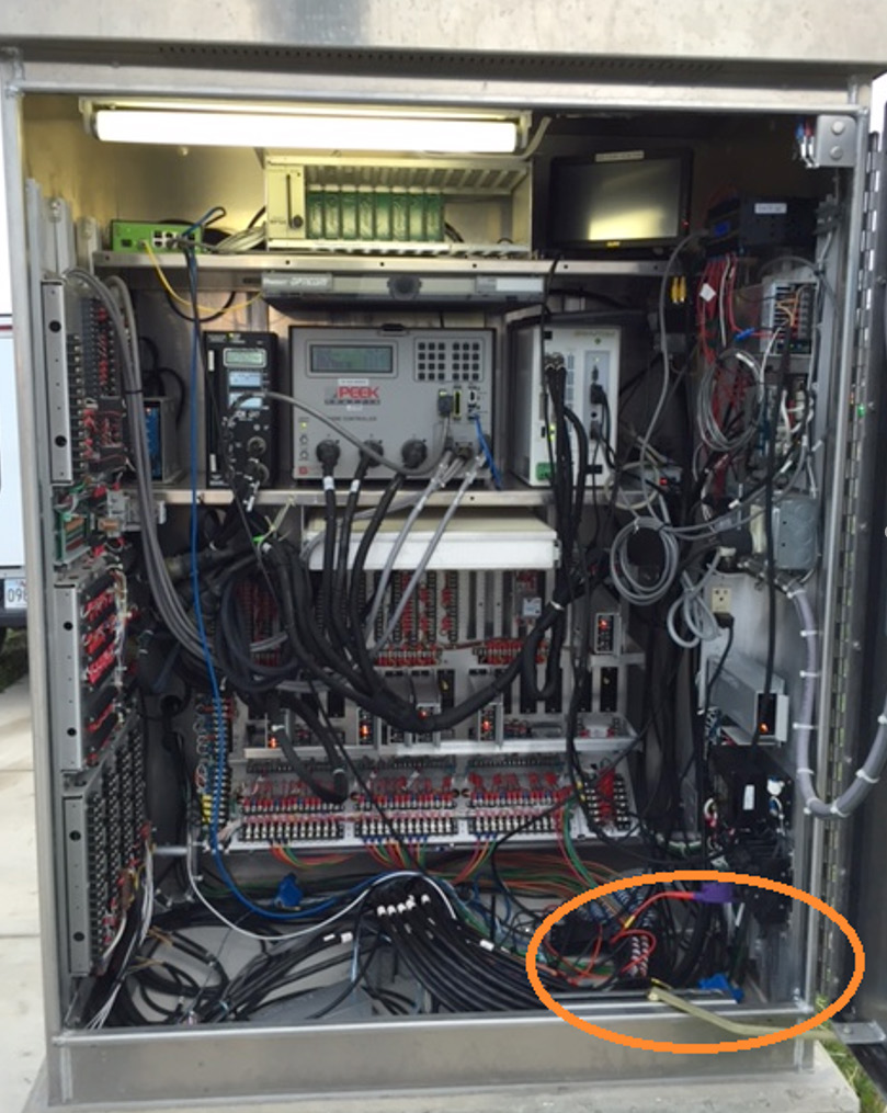
A modern traffic signal cabinet (Figure 1) has many components. The utility voltage is typically supplied from a small 240V single-phase distribution transformer, with a single 120V leg powering the cabinet. Less commonly, the voltage may be tapped from a 120V phase of a nearby 3-phase commercial/industrial customer transformer.
Entering the cabinet, the first PQ component encountered is typically a surge suppression system. Its primary purpose is to squelch transients and sub-cycle voltage excursions that significantly exceed the maximum expected peak voltage. Designs vary, but some systems also include high frequency noise filtering. This filtering can be very helpful in preventing problems from powerline communications systems.
The next component in the chain is a UPS. Not all cabinets include a UPS, but it’s often introduced to provide backup power during a brief interruption, and also in the hopes that it may provide some immunity to utility PQ problems. The UPS, while essential if power during an interruption is needed, greatly complicates PQ troubleshooting.
With a UPS installed, the traffic agency effectively becomes the “electric utility” inside the cabinet. This is especially the case with a “double conversion” UPS (described below), which is always providing the 60 Hz voltage to the load.
In many cases, the power distribution wiring inside the cabinet is as complex as that from the substation to the revenue meter, with just as many possible failure points. One of the first questions that should be asked when a PQ issue arises is whether the problem originates from the utility or inside the cabinet. The UPS is usually the focal point of that query.
The primary load in the cabinet is the traffic signal controller. The programmable controller provides all timing and switching logic to the traffic signals. The controller delivers the outputs to drive each traffic signal at an intersection. Older controllers were based on electromechanical relays and analog timing circuits. The latest controllers are essentially embedded computer servers with slots and ports for communications and a wide variety of accessories.
A key accessory of the controller is the Malfunction Management Unit (MMU). This electronic device detects conflicting signals or output conditions of the controller and locks the intersection into a safe mode (e.g. flashing yellow or red on all directions) until manually reset. The MMU also provides logging capabilities. Most traffic cabinet troubleshooting starts with clues and actions taken by the MMU. These clues then lead back to the UPS or utility.
A typical cabinet is filled out with other devices such as network routers and modems, motion sensing accessories, video camera servers, etc. While these are important, the primary components of the cabinet in terms of key functionality and PQ troubleshooting are the traffic controller, MMU, and UPS.
UPS Architecture
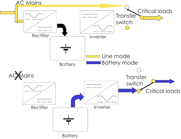
Although there are many designs on the market, there are two major types that impact PQ troubleshooting: offline and double-conversion. An offline UPS (outlined in Figure 2) routes utility voltage to the load during normal operation. Utility voltage is also supplied to the battery to ensure it’s fully charged. If a utility outage is detected, the UPS switches the load to its internally generated AC supply created by the inverter. When utility voltage is restored, the load is switched back to the utility voltage.
Because the UPS is intended to switch only during a real outage, the inverter sine wave is not synchronized to the utility waveform. Because the utility voltage is supplied to the load, there is no PQ mitigation, voltage regulation, etc. provided by the UPS during normal operation. The offline architecture is simple and low cost.
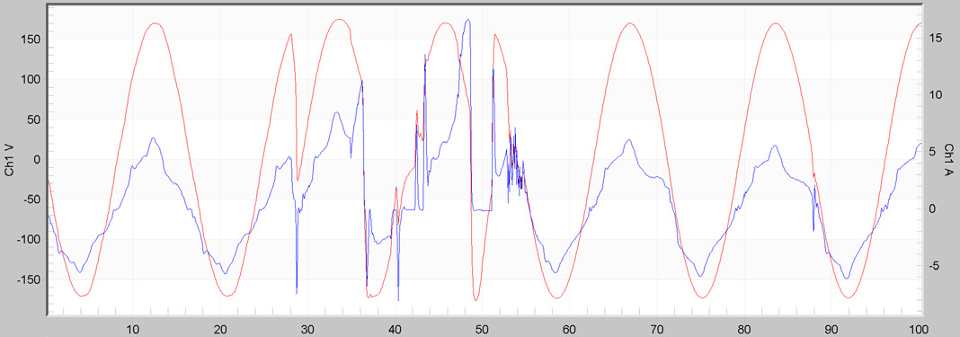
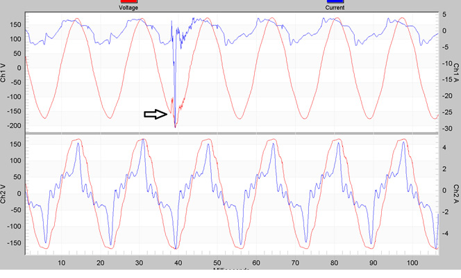
In some cases, an offline UPS may actually amplify the effects of a small utility disturbance. In Figure 3, waveforms from an offline UPS output supplying a traffic controller are shown. The top trace is the normal output, which is essentially the utility voltage due to the UPS architecture. The middle trace shows the UPS quickly switching from utility to inverter, and back again, based on no real PQ issue from upstream.
The third trace is a repeated occurrence by the UPS over several cycles. The UPS is switching to backup power unnecessarily, sensing that utility voltage is still present, then switching back, all in the same second. This operation may be triggered by routine distribution transients such as capacitor bank switching, upstream breaker operation, tap changes, etc. A small sub-cycle waveform event that would normally be harmless for the controller may confuse the UPS, causing it to switch to inverter, and back to utility voltage. The inverter voltage is not synchronous with the utility waveform, resulting in discontinuities and out of tolerance voltage delivered to the controller. The bottom waveform in Figure 3 is likely to cause a sensitive traffic signal controller to reset, forcing the MMU to lock out the intersection. Thus the UPS is making the PQ situation much worse and the controller would be better off without it unless there’s a real outage.
More sophisticated offline UPSs have settings to help prevent this problem. With settings for a minimum time before a switch to the inverter, minimum time before switching back, voltage thresholds, etc. may all be adjusted to reduce misoperation based on non-outage events. If routine utility events are causing a UPS to switch unnecessarily, examining these settings are a good first step. Bad connections at the service drop or inside the cabinet are another source of intermittent disturbances that may cause excessive UPS switching. Recording voltage waveforms on both the UPS input and output can provide clues for why the UPS is switching and what effect that may have on the controller.
The second UPS type is known as “double conversion” (Figure 4). Here the UPS is always providing power to the load from its own inverter. The utility voltage is rectified to a DC bus, which is used to power the inverter block and charge the batteries. A bypass switch allows for manual utility passthrough, but in normal operation, the inverter output is directly powering the controller. If there is a loss of utility voltage, the batteries seamlessly provide power to the DC bus. There is never a switch from one sine wave output to another, and in theory, the load never sees a UPS switching event. Because the utility waveform is rectified to a smoothed DC bus, most transients, voltage sags, and other PQ issues are blocked at this point. The RMS voltage is regulated by the inverter, so utility line voltage regulation is also not an issue for the controller, as long as the UPS itself is able to run. This type of UPS is significantly more expensive but does provide some advantages for PQ mitigation.
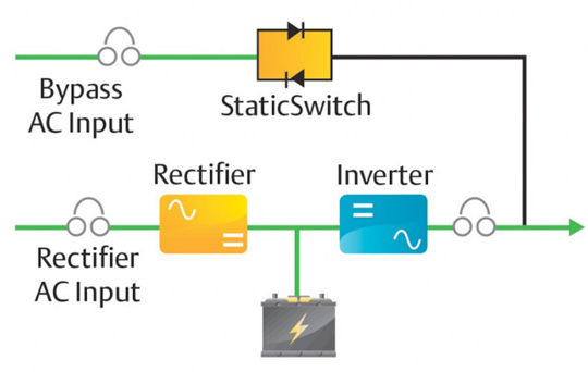
Figure 5 shows a utility switching event on the top trace (UPS input), and the UPS output on the bottom trace. The UPS output seen by the controller shows no sign of the event. The input current (blue) spikes at 30A peak compared to the normal 5A – likely due to surge suppression clamping the peak voltage. This could eventually degrade the surge suppression devices, but in the short term, the UPS is providing PQ mitigation. Here true voltage waveform anomalies seen by a controller are more likely due to wiring or UPS problems inside the cabinet.
A key item to note is that it’s very important to monitor both sides of the UPS – input and output. With both architectures, the voltage seen by the controller is possibly much different than what’s supplied by the utility. Most PQ complaints will stem from controller misoperation flagged by the MMU, without any indication of the problem source. The trigger to a problem may originate with a utility event, but the root cause is poor UPS operation. A failing UPS will often present voltage anomalies to the load, without any upstream trigger.
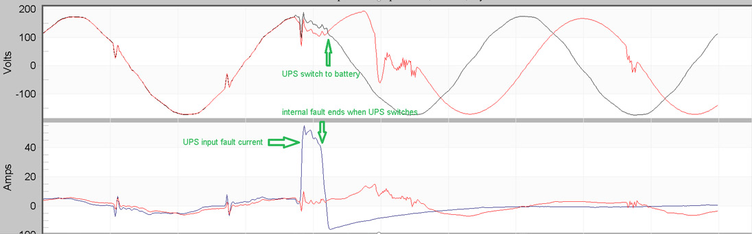
In Figure 6, an intermittent fault within the UPS at the peak of the voltage waveform is triggering excessive UPS switching. The top plot shows input (black) and output (red) voltage, and the bottom plot shows input and output current. The UPS input current spikes to over 40A due to an internal fault, pulling the voltage down. The voltage sag causes the UPS to switch to backup. Because the output is not synchronized to the utility, the input and output voltages are out of phase at this switching point, and the RMS voltage during this switchover is not consistent. This fault occasionally resets the controller, and the initial complaint is frequently poor power quality. Monitoring input and output voltage and current reveals the root cause.
Monitoring Recommendations
Often the first symptom of a possible traffic PQ problem is an intersection with flashing red signals in all lanes. The MMU detects conflicting signals or a reset controller and locks it out. Logs from the MMU or UPS show “Power Interruption”, with no further details. If a timestamp is available, look for correlations with any utility switching operations or powerline carrier meter reading.
The monitoring location determines the ideal PQ recording setup. If outside the cabinet (transformer secondary or revenue meter base), monitor all 120V legs, even if only one is used by the cabinet. Use iron core TLAR clamps on the 20A range for the best current resolution (cabinet load is usually just a few amps RMS). If inside the cabinet, monitor both the voltage and current inputs and outputs of the UPS. As discussed above, the UPS is a focal point for power quality investigations, as both a possible source and mitigator. Keep in mind that the network, from the UPS to the controller, is essentially a small power distribution network itself.
The stripchart interval should be relatively short – no longer than 1 minute, and ideally between 1 and 10 seconds. The finer time resolution allows for accurate logging of back-to-back UPS operations. The key stripchart data types to enable are RMS voltage, current, and THD (Figure 7). PMI’s Revolution or Guardian provide ITIC/CBEMA logging may be very helpful. The controller manufacturer will likely adhere (and fall back on) to the ITIC compatibility graph, and events outside of the standard may not be tolerated.
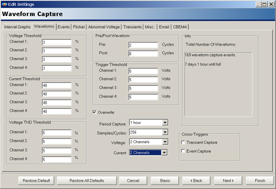
Waveform capture may be the most important data type, revealing if the UPS or utility is the root cause of a PQ issue. Recommended settings are shown in Figure 8. Limit the channels to only those connected to maximize recorder memory (in this case, 2 voltage, 2 current). Enable periodic capture to guarantee baseline waveforms – good choices here are 1 hour or 4 hours, depending on the length of the recording. The default voltage triggers are a good starting point for 120V monitoring.
A cell-based Revolution or Guardian allows for email/SMS notifications on PQ events, and remote download if there’s a traffic signal complaint after installation. Remote communication eliminates the need to coordinate with the traffic agency to open cabinet just to download a recorder.
Conclusion
Traffic signal cabinets play a critical role in today’s society. A modern cabinet often contains an entire power storage and distribution system, along with sensitive, complex loads, and a “watchdog” device ready to lock the system out on misoperation. The voltage monitoring and logging provided by cabinet devices are rudimentary, and at best may only suggest a PQ problem. Understanding the cabinet power architecture, especially inside the UPS, is needed to quickly diagnose and solve a PQ problem and determine whether the cause originates inside or outside the cabinet. An overview of cabinet internals is given here, along with implications on PQ monitoring. Recommendations for PQ monitoring are also presented.
