Abstract
This paper explains some of the issues concerning power factor correction, and the side-effect of resonances that can be detrimental to a power distribution system. Also are some solutions to head off issues caused by parallel resonance and problems such as blown capacitors, tripped breakers and fuses.
Interaction of Capacitors and Resonance
In the power industry, one engineering goal is to make the power distribution system as efficient as possible. One way to improve the efficiency is to make sure that the power factor is the best it can be in a particular location. Power factor, the ratio of real power to apparent power, is a measure of how efficiently the current being transported is delivered as actual billable power. With an AC voltage source, inductive or reactive loads result in a phase-shifted current waveform, and this phase shift results in reactive power flow, which is unbillable and does not contribute to useful work. Also, poor power factor wastes resources for both the utility and the end user, by loading transformers with reactive power (increasing heating) decrease grid capacity, and increases wire I2R losses. Traditionally, most loads are either resistive or inductive. To correct the power factor with an inductive load, a capacitor may be installed to counteract the inductive impedance. If the location is at a site that has large loads that are very inductive, as in locations with many large motors, the payback time for installing capacitor banks can be very short. Sometimes, however the power factor correcting capacitor banks can actually cause or aggravate other power quality issues due to resonances. Solving a power factor issue by adding capacitance can sometimes cause a harmonic resonance issue.
Resonances happen when the capacitive reactance becomes equal to the inductive reactance at a specific frequency. As the frequency increases, inductive reactance also increases while capacitive reactance decreases. There will be a crossover point where the reactance of the capacitor exactly equals the reactance of the circuit’s inductance. This frequency, FR, is called the parallel resonant point. The frequency, FR, occurs when XL=XC, where XL is the inductance portion of the system, and XC is the capacitive portion (generally the inductance is the substation transformer plus loads, and the capacitance is from power factor capacitors). Solving for FR results in the formula below.
All power distribution systems with power factor correction capacitors have a parallel resonant point at some frequency, typically between 200 and 700 Hz. In actuality, there are often several resonance points. If there are multiple capacitors, there is a resonance frequency created for each capacitor’s XC matched with the aggregate inductive load XL. In addition, each parallel combination of capacitors creates yet another resonance. The resistance between sets of capacitors limits the sharpness of the resonance, so that in many cases the secondary resonances are not important. Each inductive load also resonates separately with each capacitor, and in theory there is a separate resonance for every combination of load inductances and capacitances.
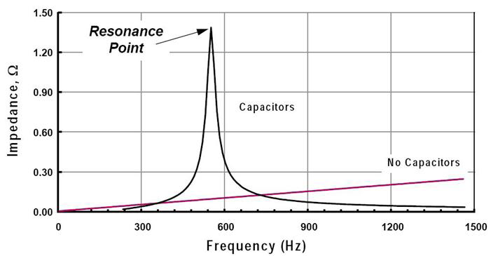
Figure 1, In the graph above show how a PF capacitor can cause a resonance point.
The sharpness of the resonance is determined by the amount of resistance between the capacitor and resonating inductance. A power factor capacitor physically near a large motor may produce a very sharp resonance. A capacitor with miles of distribution wiring and resonating with widely separated aggregate inductive loads will produce a resonance barely measureable, and unnoticeable.
It is important to note that parallel resonances create issues only if it’s excited by a source. This excitation can come from a harmonic voltage or current at the exact resonant frequency. Or, an impulse transient or abrupt step change in voltage or current (which has a wide spectral content, including the resonance frequency), can excite the resonance. The former tend to be steady state PQ issues, while the latter are one-time or intermittent events. In Figure 2, an apparent upstream line-line fault occurred. This step change in voltage excited a resonance, producing the ringing shape. This ringing continued for a short time. The toggle point table can be used to estimate the period, and hence the frequency, here around 1191 Hz, close to the 20th harmonic. The excitation was a one-time event, so the resonance is only noticeable at that time. Unless significant 20th harmonic voltage or current appears from another source, the resonance is otherwise benign.
System Impedance
The system impedance at the resonant frequency can result in actual circuit gain, multiplying the harmonic voltage or current by up to a factor of two in the case of a very sharp resonance. Currents and voltages are much higher than normal which put stress on circuit components, such as the capacitors themselves. It would be very unlikely that that these two frequencies (the resonance frequency and the frequency of the harmonic) are exactly identical, however, even if they are close, damage can occur. With a sharp resonance, the exact frequency may shift with time of day, as loads change, or disappear entirely if a specific key load is powered off, producing an intermittent resonance problem.
The above formula gives an estimated resonance frequency based on the system short circuit rating and the capacitor VAR rating. Both of these measures indirectly relate to system inductance and PF cap bank capacitance, and can be used to estimate the resonance frequency. For example, if the source capacity at a substation is 10 MVA, with a capacitor bank rating of 120 KVAR, when you use the equation in the previous formula, it calculates out to equal to 547 Hz, close to the 9th harmonic (540Hz). This indicates that the capacitor bank will be resonant with the source impedance at approximately the 9th harmonic. If there is a substantial amount of 9th harmonic current from nonlinear loads, or 9th harmonic voltage (possibly from upstream), the resonance will be excited, with increased voltage or current. Damage may occur if the resonance is sharp enough, or the frequencies match closely enough. Even without damage, there may be a temporary loss of power due a tripped circuit breaker or just a blown fuse however it could cause more catastrophic results as a damaged capacitor, even a transformer failure or fire.
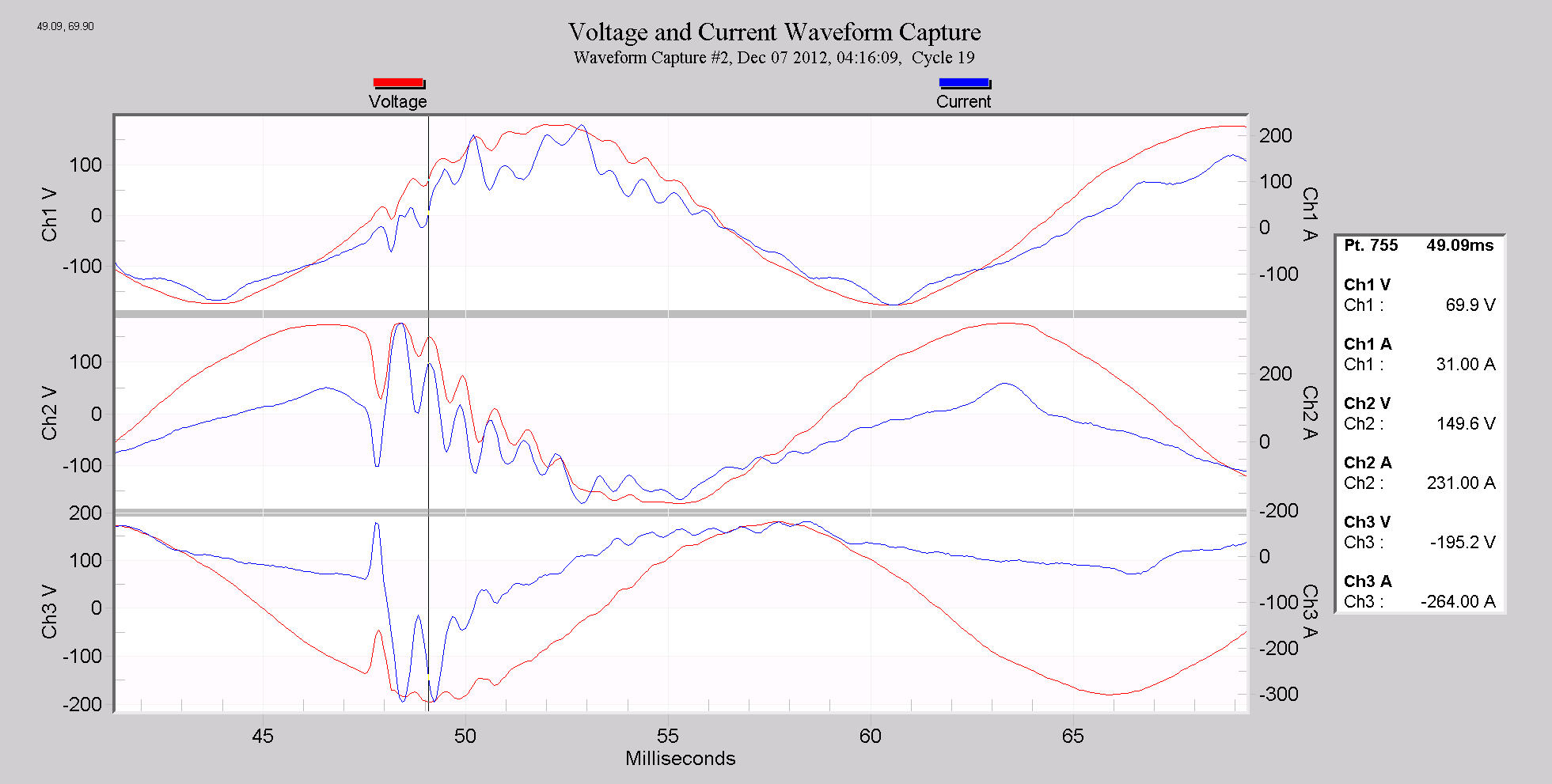
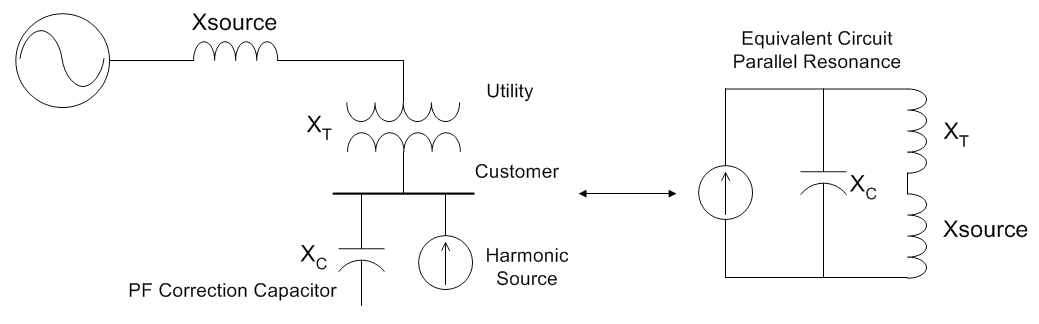
Figure 3 presents an example of how adding a PF capacitor caused a parallel resonance with the existing circuit’s inductance. Because the kVAR rating of a capacitor is directly proportional to the capacitance, the resonant frequency (for a specific circuit inductance) varies with the kVAR rating. Sometimes an inline fuse with a capacitor may open up, removing the capacitor from the circuit. This could change or even eliminate an existing resonance issue, but leave the power factor uncorrected. This may happen; however, this defeats the purpose of the capacitor. Instead, the system should be designed to avoid a resonance at the problem frequency.
It is important to know what the over voltage and over current limits are, considering what specifications are listed on the capacitor’s nameplate. The IEEE Standard 18-2002 states that shunt power capacitors must be able to withstand a maximum continuous RMS overvoltage of 110% and an over current of 180%. It also states that the VA rating of a capacitor cannot exceed 135%. It is good engineering practice to add an extra margin of the capacitor’s full load current. This extra margin will help to ensure that over current protection systems will not engage during the initialization of the capacitor when the circuit is energized – energizing a capacitor is a very abrupt step change, and will excite any resonance formed by that capacitor.
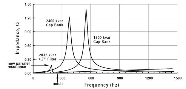
It is important to avoid sharp resonances whenever possible to head off systems issues. One way to resolve resonance issues is to de-tune the resonance by adding a harmonic filter or to make sure the proper size PF capacitor is installed to avoid resonances that fall in known harmonic trouble spots altogether. Harmonic filters act similar to capacitors as far as providing the same 60 Hz reactance, however, they are designed with a parallel resonance point below any expected harmonics of the system. In Figure 4, two capacitor banks are shown with very sharp resonances. A third bank (2032 KVAR) is shown, but with a notch filter at the 4.7th harmonic, greatly reducing the resonance with the rest of the system. For more information on recommended practice for harmonic control in power systems, please refer to IEEE-519. This document contains a wealth of information for evaluating and controlling harmonic resonance and harmonics in general.
Recording Data for Resonances
To gather data relevant for resonance issues, waveforms and harmonics are required. Waveform captures can reveal resonances triggered by step changes, faults, recloser or capacitor switches, etc. To catch these events, use THD triggering to capture waveforms based on waveform shape changes (available in the Revolution). For steady state issues, record at least THD, but ideally odd lower-order harmonics to see specific harmonic levels. This will be required if a tuned filter is needed.
Conclusion
It is always the desire of any power company to eliminate or reduce reactive power, and thus improve power factor, and to improve overall system efficiency along with reducing the systems cost. It is however very important to evaluate the system carefully determining how the power factor correction capacitors can add resonances to the system, increasing problems with harmonics and overvoltage during transients. Be sure to account for the system’s kVAR when determining the capacitor’s working voltage to keep from exceeding the capacitor’s voltage specification if a resonance would happen to occur. It is important to heed the IEEE Standard 18-2002 when determining a capacitor’s voltage rating for a given system. In this paper I tried to touch on some of the basics, for more detailed information, please consult the IEEE Standards 519, the Recommended Practices and Requirements for Harmonic Control in Electrical Power Systems. Recording waveforms and harmonics gives the data needed to find resonance problems.
