Introduction
When three phase systems are perfectly balanced sinusoidal waveforms, where the B and C phases are exact replicas of the A phase sine wave, but delayed by 120 and 240 degrees respectively, then the analysis of the system is relatively straightforward. Any calculations can be performed on the A phase and then just time delayed by a third of a cycle to calculate the quantity for the B phase and another third of a cycle for the C phase. Nothing really happens in this setup that is very strange if one has a basic understanding of AC circuit theory.
Unfortunately, real world three phase systems are not perfectly balanced sinusoids. Sometimes they are a few degrees off from what they should be, sometimes one phase is higher than the other two, sometimes there is unequal waveform distortion, sometimes there is more capacitive coupling with the ground on one phase compared to the others, and sometimes a fault occurs that only affects one phase, leaving the others untouched. All of these situations make the math very challenging both to solve and to describe anything useful about the system.
This paper describes a mathematical tool called symmetrical components that greatly simplifies the analysis of real world three phase systems. This method of symmetrical components is used throughout the field of power engineering with applications in fault analysis, motor control, and power system stability.
Review of Phasors
To understand symmetrical components, it is instructive to review the construction of phasors. The first thing to observe is that a point spinning around an axis at a constant rotational velocity generates a sine wave of some frequency, amplitude, and phase by simply projecting the point onto an axis perpendicular to the axis of rotation and recording a time series plot of the projected value.
This spinning point can be represented in the complex plane by a complex exponential such as A·ej(ωt + t₀) or A·ejt₀·ejωt
It turns out that pointwise addition of sine waves of the same frequency corresponds exactly to projecting up to two complex numbers spinning at the same speed, adding them as complex numbers, and then projecting back down to the axis. This correspondence between pointwise addition of sine waves and addition of spinning complex numbers justifies the mathematical association between the two. The last step is to realize that all spinning complex numbers derived from sine waves of the same frequency each contain a factor of ejωt with the same ω and that factor can be pulled out and ignored. Thus once a particular frequency is chosen, usually it is the 60 Hz line frequency, then there is a direct relationship between sine waves with a particular amplitude and phase shift and between complex numbers with a particular magnitude and angle, off the x axis.
Derivation
It is a common strategy in mathematics to represent complicated objects by a sum of simpler objects. In the case of three unbalanced phases, the idea is to break them up as a sum of different sets of balanced phases. Each set of balanced phases will have equal amplitude and the phase shift between the phases will be an integer multiple, called K, of 120° from each other. There are three different ways that this set of balanced phases can be constructed. The first way is called the Zero Sequence, when K = 0, and that happens when all three phasors point in the same direction. The second way is called the Positive Sequence, when K = 1, and that happens with the ABC pattern when phase B lags phase A by 120° and phase C lags phase B by 120°. In the complex plane, because the ejωt term that was factored out spins everything counterclockwise, this might look like phase A on the x axis, phase B in the third quadrant with negative imaginary component, and phase C in the second quadrant with positive imaginary component. The third way is called the Negative Sequence, when K = -1, and that happens with the ACB pattern when phase C lags phase A by 120° and phase B lags phase C by 120°, resulting in a clockwise rotation in the complex plane compared to the counterclockwise rotation of the positive sequence.
Each of the Zero Sequence, Positive Sequence, and Negative Sequence will have a complex number coefficient, which will be called V₀, V₁, V₂ and this coefficient describes the magnitude and phase shift of each sequence of phasors. The phasors of the original unbalanced system are given labels of VA, VB, VC
Another notation that will be helpful is to define α as:
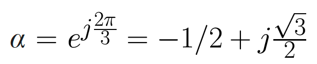
Which represents through complex multiplication a counterclockwise rotation in the plane by 120°. α2 represents a 240° counterclockwise rotation and α3 = 1 represents the null rotation. In order to determine what V₀, V₁, V₂ must be, 3 equations need to be written down, one for phase A, one for phase B, and one for phase C.
The equation for phase A is VA = V₀ + V₁ + V₂
The equation for phase B is VB = V₀ + α2·V₁ + α·V₂
The equation for phase C is VC = V₀ + α·V₁ + α2·V₂
These can all be written succinctly in a matrix as

This system can be solved by inverting the matrix yielding

Example
Suppose there is a nominally 120V three phase system where:
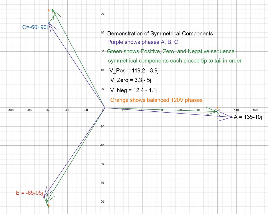
The A phase has phasor 135 − 10j (135.4∠−4.2°)
The B phase has phasor −65 − 95j (115∠−124.4°)
The C phase has phasor (−60 + 90j) (108.2∠123.7°)
Then the symmetrical component coefficients can be computed:

The following figure shows a plot of this example. The phases are plotted in purple and the 120V balanced phasors are shown as orange dots for reference. The Symmetrical Components for this example are plotted in green as three different paths of three arrows.
- The first and biggest set of arrows emanating from the origin are the positive sequence arrows. Most of the information about the phases is contained in this positive sequence of vectors.
- The second set of arrows placed at the heads of the positive sequence arrows are the Zero Sequence vectors, which all point in the same direction.
- The third set of balanced phasor arrows, placed at the tips of the Zero Sequence arrows are the Negative Sequence arrows.
It is important to notice that for each of the three unbalanced phases, the positive sequence part plus the zero sequence part plus the negative sequence part sum to be exactly the chosen phase vectors.
Unbalance
Unbalance is defined as the ratio of the magnitude of the negative sequence component to the magnitude of the positive sequence component in a three phase system. The zero sequence component is a measure of the neutral conductor shift in a Y-connected three phase system and does not contribute to unbalance between the phases. Because Delta connected systems do not have a neutral, the zero sequence component is always 0 in those systems. This unbalance ratio is a useful measure of how different a three phase system is from the ideal balanced case. In the above example, the unbalance is 12.5/119.3 = 10.5%, which is unusually high. The example was chosen to exaggerate the zero sequence and negative sequence contributions, because they are usually invisible on the same scale as the positive sequence.
In motors, a negative sequence voltage will induce a negative sequence current which will try to spin the motor in the opposite direction and will impact the efficiency of the motor. In transformers, a negative sequence current will counteract the positive sequence transfer of energy and will lead to higher core and conductor losses.
It should be noted that while voltage unbalance is a useful system metric and quantifies real equipment effects, current unbalance is usually not as useful. A much better metric for current is the magnitude of the negative sequence component without making it into a ratio. An example will help illustrate why. Suppose a large factory operates with many large well balanced three phase machines. They might operate regularly with a voltage unbalance less than 2% and a current unbalance less than 5%. If the factory decides to shut down at night, but someone accidentally leaves a desk lamp on, suddenly the current unbalance jumps up to 100% because only a single phase is delivering any power, even though the total current drops to basically nothing during this time. This radical jump in current unbalance does not indicate any kind of harmful effect or problem. It would be much better to focus on total negative sequence current which would be much higher when the plant is in full operation.
When diagnosing power quality problems, it can be beneficial to look at a stripchart where voltage unbalance is plotted together with negative sequence current. If the two plots correlate well, then it is clear that the load downstream of the current meter is causing the voltage unbalance effect. If they don’t correlate, then something else on the feeder is causing voltage unbalance.
Conclusion
The method of Symmetrical Components is a useful mathematical tool to analyze three phase systems that are not necessarily perfectly balanced. It works by representing the three phases as sums of Positive ABC Sequence, Negative ACB Sequence, and Zero Sequence balanced phasors. Each sequence contains useful information for Power Quality Engineers that is difficult to observe by simply looking at the phases themselves and these sequence coefficients are used to establish other metrics like unbalance. This method is crucial for diagnosing faults and improving equipment performance.
