Abstract
PMI offers a fused voltage lead kit for increased safety with the Revolution and Eagle power recorders. Although not required to meet UL safety standards with these recorders, the fused lead kit can provide an extra layer of protection from arc flash and other hazards possible with a short circuit in a CAT III/IV location. The best practices and advantages of using PMI’s external fused lead kit are described in this whitepaper.
Overcurrent Protection Basics
A fuse is designed to prevent equipment damage or injury from either short circuits or overvoltage that result in excessive current. A fuse is a “sacrificial” component; when the current flowing through a fuse exceeds its threshold (specified in terms of current and time) the fuse blows. A blown fuse is an open circuit, preventing any further current flow.
A fuse protects equipment by isolating the equipment from incoming damaging voltage transients and overvoltage conditions. A voltage clamping surge suppression device is often used in conjunction with a fuse. In the case of a transient, the surge suppressor clamps the voltage to a level that will not damage the device. However, these suppressors are limited in the amount of energy they can absorb. The fuse is manufactured to blow before that limit is reached so the equipment is protected. The voltage event is long over by the time the fuse is replaced, and the device can continue working.
A fuse protects the user by preventing overheating from excessive current produced from a short circuit or other internal component failure. “Excessive” current can range from enough to eventually cause a fire over many minutes (e.g. tens of amps) to severe arc flash explosions (e.g. thousands of amps). In this situation, the equipment has already failed – the fuse’s job here is to prevent that failure from becoming dangerous. If the fuse is replaced and voltage is applied, the original problem will usually continue to draw excessive current and blow the next fuse. The problem must be addressed before the device can be used.
Recorder Protection Architecture
A Revolution or Eagle provides protection in two ways: an internal fuse, and high impedance voltage inputs (see Figure 1). Each voltage measurement input uses a network of large resistors that present very high impedance to neutral (and to each other). UL safety standards require that a single component failure anywhere in the device must not result in a hazard. A shorted resistor will produce a lower, but still high impedance to the outside of the recorder. The resistor network meets this UL safety requirement and is considered safe in the listed voltage environments (CAT IV for the Revolution, CAT III for the Eagle) without external fusing. The high impedance inputs limit current in the event of an internal short circuit, and also limit any excessive incoming current from external voltage transients.
The Revolution and Eagle are powered from the channel one voltage input. Consequently, an internal power supply is connected between the channel one input and the common (black and white banana jacks respectively). Unfortunately, a power supply inherently cannot have a high impedance because the impedance would prevent any appreciable power from being delivered. Instead, a fuse is needed for overcurrent protection. An internal fuse provides this for the power supply circuitry. The fuse and power supply are in parallel to the channel one high impedance resistor network (as shown in Figure 1), and both the fuse and high impedance provide protection independently for different types of failures and external events.
Using the PMI fuse kit adds supplemental protection with the presence of a fuse in series with each voltage lead. For channel one, the lead fuse is in series with the internal fuse (Figure 2). Although the Eagle and Revolution already meet UL standards for safety, the fuse kit provides additional overcurrent protection in three areas:
- The high-impedance inputs, in case of simultaneous multiple internal faults.
- The common input to the power supply, which is not high impedance.
- The test leads themselves (provided that the fuse is at the dolphin clip end).
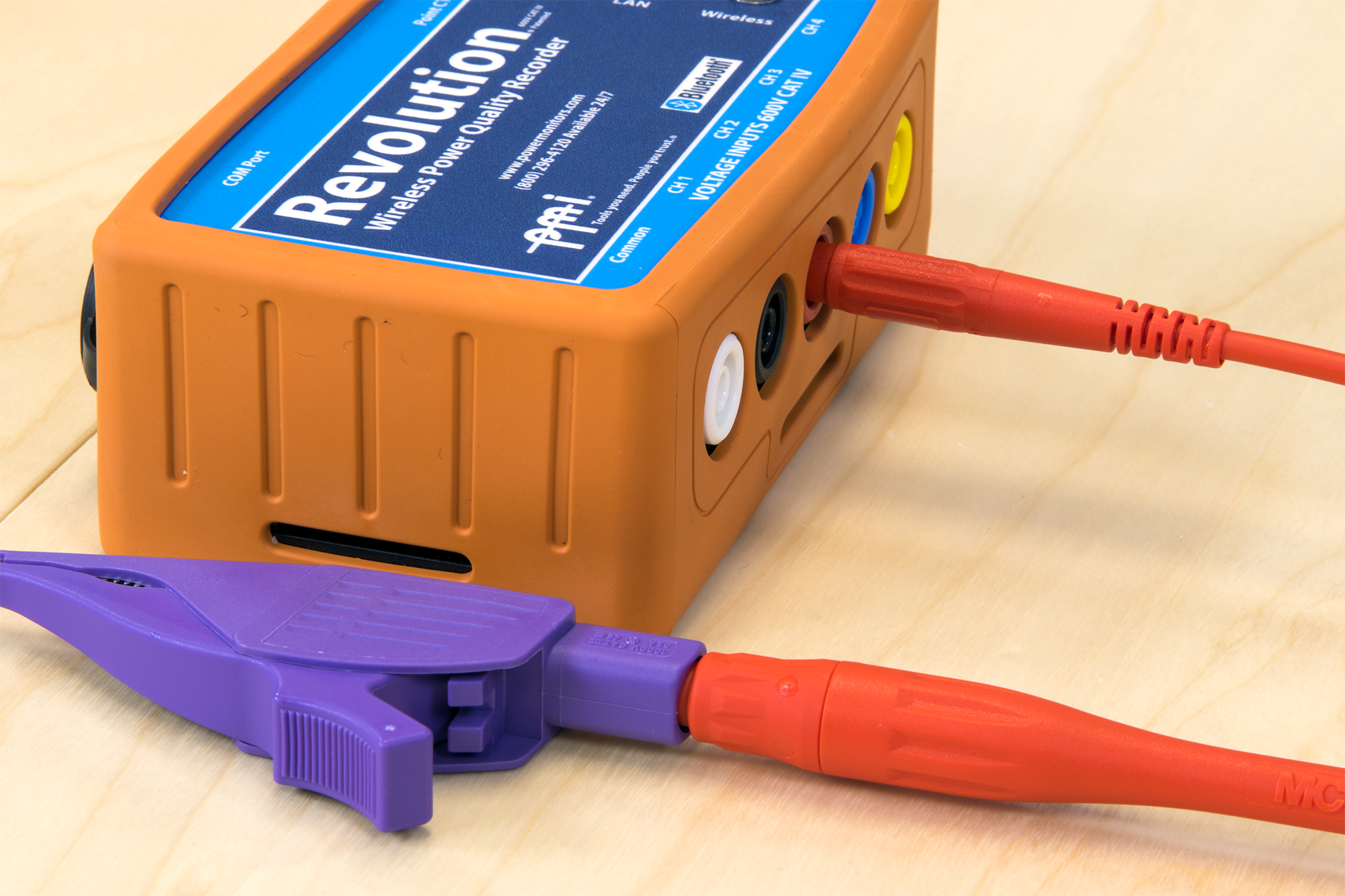
The last item is perhaps the most important. The voltage leads are outside of the Revolution and Eagle fuse/high impedance system, and are also vulnerable to nicks in the insulation (being pinched by a metal panel cover, etc). Using a fuse in each lead protects the entire voltage path, from the end of the dolphin clip back. Note that installing the voltage lead with the fuse near the PQ recorder doesn’t provide this protection, since the test lead is electrically ahead of the fuse (Figure 2). Be sure to plug the fused end of the lead into the dolphin clip to protect the test lead itself, as shown in Figure 3.
PMI Fuse Kit
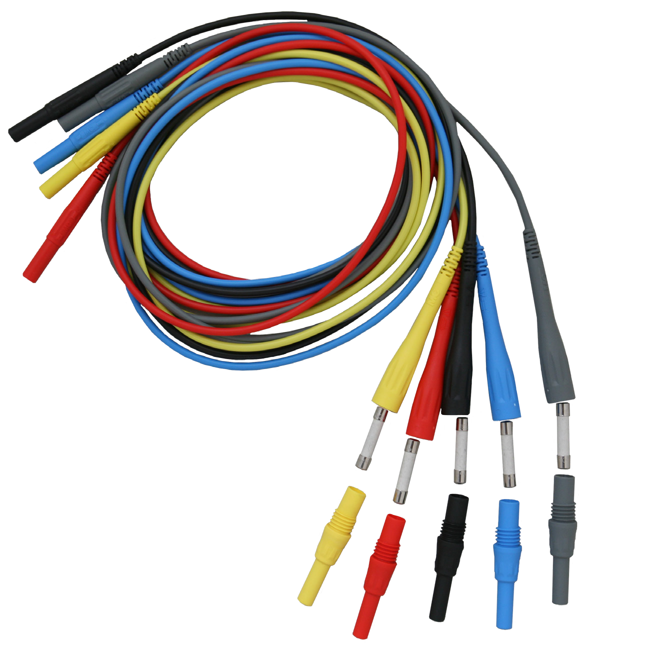
The PMI fuse kit is composed of five color-coded voltage test leads, each with an internal fuse (Figure 4). The leads are rated for 600V CAT IV use, to match the ratings of the recorder. Each lead contains a Littelfuse 508 series cartridge fuse. This fuse has three key specifications that are important in this application:
- 1000VAC rating
- 1 amp threshold
- 10,000 amp interrupt capability
The fuse’s voltage rating must be at least 600VAC for use with the Revolution and Eagle. A fuse may not interrupt the overcurrent if the voltage across it exceeds the fuse rating. The 1 amp threshold is the minimum current that will blow the fuse. This value must be compatible with the power supply requirements (including any in-rush current, etc.) of any device that draws power through it. One amp is sufficient for the power supply of both the Revolution and Eagle. Finally, the 10,000 amp interrupt rating specifies that the fuse can actually break a short circuit of up to 10 kA. Many small fuses that might fit in a voltage test lead assembly have a much lower interrupt rating, but 10 kA is needed for CAT III and CAT IV locations, where very high currents are possible with a dead short.
The fuse is located at one end of the test lead (the larger end, see Figure 4). To expose the fuse, unscrew the banana plug from the end of the lead. The fuse may be pulled out of the plug to be checked or replaced. If a fuse blows, it’s best to obtain a replacement fuse from PMI; in any case the fuse must at least meet the specifications above. The Revolution is available with high-speed transient capture which adds 1 MHz voltage sampling and a +/- 5 kV transient input range. In situations where large transients are possible, the external lead fuse may blow on a transient applied to the channel 1/power supply input that the Revolution itself can measure. To avoid this, a non-fused lead may be used on channel 1, with overcurrent protection provided by the Revolution’s internal fuse.
Blown Fuses
In the case of an overcurrent that blows a test lead fuse, there may be no outward sign of damage. The first step in any blown fuse situation is to assume that the root cause of the overcurrent may still be present, and proceed safely with that assumption until proven otherwise. Inspect the test lead for insulation breaks or damage, and also the PQ recorder itself for any signs of failure.
An external high voltage transient or internal power supply failure could cause the channel one or common lead fuse to blow. To test the recorder, another fused lead can be substituted (or the fuse in the original lead replaced). This should be done in a controlled meter shop environment, ideally with an energy-limited AC power supply. Keep in mind that the PQ recorder’s internal fuse may also be blown.
If a high-impedance input lead (i.e. channels 2, 3, or 4) has a blown fuse, the most likely culprit is the test lead itself. The test lead should be inspected carefully for insulation breaks.
In any case, if two fuses blow in a row on the same PQ recorder input, the recorder itself is likely damaged, and should be returned to PMI for evaluation.
Do not replace the test lead fuse with any type except one that meets or exceeds the specifications above. These may be obtained from PMI.
Conclusion
The PMI test lead kit provides supplemental protection for the Revolution and Eagle, and in particular for the voltage leads themselves. In everyday use the leads are as simple to use as non-fused leads, but understanding their function as described here ensures that the extra safety they can provide is maximized.
