Abstract
PMI supports two types of current probes for measurements: Rogowski coil and iron-core clamps. Their distinct properties and characteristics need to be considered in a particular situation to better the measurements taken. The properties of each probe type are described here, along with best practices to maximize the quality of the data recorded.
Current transformers (CTs) operate under the principal where flux lines developed in the core are shared between the primary and secondary CT windings. Since both windings contain an equivalent flux their Ampere-turns must also equate. The CT primary “winding” is typically a 1-turn winding formed by the conductor under measurement, which is contained by the clamp jaw. The secondary winding is internal to the clamp, and is usually in the range of 200 to 1000 turns. The raw CT output is a current whose value is reduced by ratio of secondary to primary turns. This current is transformed to a voltage signal with a precision terminating resistor.
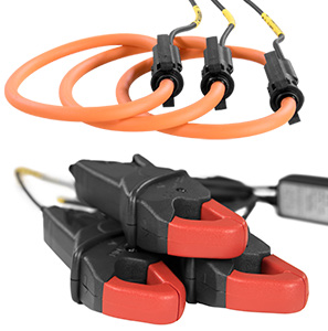
PMI’s True Low Amp Range (TLAR) current clamps are rigid iron core CTs. The copper-wire wrapped, iron-core jaws close around the conductor being measured. The iron core concentrates the imposed magnetic field generated by conductor’s AC current, which is picked up by the secondary windings. The whitepaper, Using TLAR CTs, explains in more detail the workings of TLAR CT clamps.
Rogowski coil or Flex CT is a coreless current “transformer” which consists of tight copper coils around a center conductor. The lack of a rigid structure allows the Flex CT to be installed in locations not conducive for rigid clamps. The whitepaper, Flex CT Overview, delves deeper into the history and operation of Rogowski coils. Technically these are not transformers, as the raw voltage output is proportional to the derivative of the current being monitored. The raw Rogowski coil output is integrated and amplified by electronics in the Flex CT assembly, and the end result is the same as a standard current transformer.
Starting a Current Recording
Before any measurements are taken, it is important to select the correct CT type and current range for the job. Knowing which CT to use prior to collecting data will maximize the data resolution and accuracy.
The TLAR clamps have an adjustable gain between 20A and 200A, making them applicable for low current readings, such as a secondary of a metering CT. When monitoring a 5A metering CT secondary, use the 20A range (which gives headroom for inrush current, etc.). The 200A range is used for residential or light commercial services, or individual high current loads. An iron-core CT can be damaged from overheating with severe, prolonged exposure to overcurrent conditions significantly above 200A.
Higher currents are more suitable for the Flex CT. The Flex CTs come in a variety of lengths. The 36 or 48 inch circumference Flex CTs can be utilized in scenarios where multiple parallel conductors need to be measured at once. Keep in mind the current flow of each conductor within the Flex CT as it must travel in the same direction, else their collective magnetic field will reduce. While Flex CTs already have a high maximum current rating of 5000A, they are not prone to damage from overcurrent that exceeds their rating. Operating ranges are software configurable at 100A/200A, 1000A, and 5000A.
When setting up a recording with ProVision, the desired operating range is selectable on the “Basic Screen” page during a recording initialization, shown in Figure 1. The selected option cannot be changed during a recording and are locked in at the end of the 2-minute countdown.
Initializing a recorder with a range that is too low for the loads being measured can introduce distortion to the measurements, causing waveform clipping and possible numeric overflow errors. Figure 2 demonstrates how current waveforms will clip at the peak ranges if values exceed the selected range. In this setup, the readings are initially within the acceptable range. As the current ramps up, the waveform begins to distort and cap at the maximum range. Near 130 milliseconds the measurement overflows and flips 180 degrees resulting in distorted waveforms.
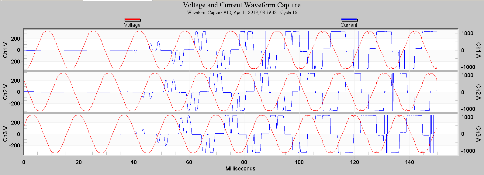
Figure 3 shows a clearer view of how clipped negative readings can wrap around and invert into a positive expressed value.
At the opposite extreme, if a situation requires more resolution it is possible to wrap the conductor around the CT to increase the number of turns, increasing the measured current respectively. For example, to measure a current under 1A max, even the 20A range may be too high for the best resolution. Wrapping multiple turns of the load conductor around the clamp jaw increases the measured current proportionally, increasing the measurement resolution. Remember to adjust the current scale factors in ProVision to compensate for the number of turns added, which can be seen in the whitepaper, Using Scale Factor in ProVision.
The selected range should never be smaller than the highest expected RMS value. If monitoring a motor start for instance, pick a range greater than the anticipated inrush current at startup rather than a range closer to its “nominal” load current.
TLAR Tips
To ensure reliable measurements the clamp jaw faces must be completely clean of all debris, grease, and rust. The clamp jaws complete a magnetic circuit through the clamp, and any gap in the jaw closure will skew the clamp output. If not tightly closed, TLAR clamps will exhibit a jarring audible noise when excited by a high electromagnetic field. These mechanical vibrations generate heat and in extreme cases may cause permanent damage to the clamps. Ensure that the clamp jaws are not inadvertently opened slightly when closing the panel cover after they’re installed.
Although safe with PMI clamps, it’s a good habit to always connect the output of an iron core clamp before clamping it around an energized conductor. An unterminated CT will traditionally have a low impedance, causing high voltage levels to develop on the secondary winding as it tries to force current through an open circuit. However, PMI’s CTs mitigate any potential high voltage exposure with a combination of built shunt resistors and metal-oxide varistors (MOV).
In general TLAR CTs are not sensitive to placement on the conductor being measured. However, in extreme cases they can magnetically couple with neighboring high current carrying conductors. Care should be taken to avoid very close proximity or physical contact with adjacent high current bus bars. If the jaw of a CT is placed in contact with a large surface area conductor, they could magnetically couple together, introducing errors in the CT output. This is much less likely with circular conductors.
Flex CT Tips
When installing the Flex CT, it is important to situate the conductor at least 1.5 inches away from the Flex CT connector. Ideally, measurements are taken with the conductor at the center of the Flex CT. In practice this is rarely possible. Instead, try to arrange the Flex CT so conductors are not near the Flex connector.
Flex CTs should never undergo a bend radius under 1 inch to avoid damage. Never yank or pull on the Flex CT while uninstalling the device. Carefully free the device from its surroundings. Excessive force could damage the CT as well as dislodge a loose energized connector.
It is possible to increase the resolution for Flex CTs in situations with low current. The whitepaper Top Ten Field Tips for PMI Recorders and ProVision demonstrates the best practices for wrapping a conductor wire around the Flex CT to help boost the resolution.
Safety
Always check for breaks in the insulation, especially on Flex CTs, as well as any cracks in the clamp body. A break in the CT insulation could create a path for an energized conductor to make contact with the PQ recorder electronics, possibly damaging equipment and presenting a safety hazard.
The TLAR and Flex CTs are rated for 600V circuits. This 600V limit applies even if the conductor to be measured is also insulated. For example, a 7200V primary conductor that has its own insulation may appear to be suitable for use with PMI CTs, since the outside of the conductor is insulated, and hence not energized. This is not the case however— the working voltage of the conductor is still over 600V, so PMI CTs should not be used in this situation. The combination of HV primary conductor and 600V CT insulation was not designed to work in combination to meet the safety levels required for use with PQ equipment.
Conclusion
Always monitor current when possible; monitoring just voltage is only half the story. Current overlaid with voltage provides much more than just double the information. Remember to select the appropriate clamp and range prior to taking measurements. Be careful during installation and ensure the clamps remain fully closed and are situated to maximize the measurement accuracy.
