Abstract
The Abnormal Voltage Report is one of the “Triggered Event” reports in ProVision and it is used to determine whether voltage drifted outside the thresholds during the recording session. Usually the Abnormal Voltage Report is used to get a quick read of whether there was any line voltage drift.
Example Report
The Abnormal Voltage Report shows the time of the first abnormal voltage high and low triggered abnormal voltage event on each channel as shown in Figure 1.

Determining Nominal Voltage
There are five standard nominals, and two custom nominals. These are controlled using software settings. Some older recorder models have LEDs on the front panel that indicated that there has been an abnormal voltage.
The recorder is initialized with a list of potential nominal voltages (such as 120, 240, etc.), with low and high voltage thresholds for each. The actual nominal is picked by the recorder during the two minute countdown. The average voltage during the countdown is compared to each of the nominals; the closest one becomes the nominal voltage for the entire recording session. There are five standard nominals in the software setup (120, 208, 240, 277, and 480 volts), and two custom nominals. The custom nominals can be set to any voltage. It is possible to enable and disable the standard and custom nominals. For example, if you wanted to force the recorder to use 230 volts as the nominal, the standard nominals should be disabled, and both custom nominals set to 230. If the standard nominals were not disabled, there would be a chance for the recorder to pick 240 volts during the two minute countdown, if the line voltage happened to be running closer to 240 than 230 at that time. The nominal is chosen by the recorder separately for each voltage channel.
Several reports, beside the Abnormal Voltage Report, use this nominal voltage for triggering events. This includes the Significant Change, Loose Neutral and CBEMA reports. This does not include the Event Change report. The Event Change Nominal voltage is specified by the user, and is not picked by the recorder.
Trigger Logic
The triggering logic uses a low and high threshold, a nominal voltage, and a trigger duration. The thresholds are added and subtracted to the nominal voltage to find triggering points. If the voltage crosses a triggering point for longer than the trigger duration, an Abnormal Voltage event occurs.
There are separate high and low thresholds for each of the seven nominal voltages. The applicable thresholds are used once a nominal is selected by the recorder after the two minute countdown. Voltage channels are handled separately; there is a complete set of nominals and thresholds for each. This is useful for situations such as a hot-leg delta, where one voltage channel is at a different voltage, or in a single phase setup where two channels are connected line-to-neutral, and one channel is line-to-line. The recorder will automatically select the correct nominal and thresholds for the different line voltages on each channel.
The last Abnormal Voltage parameter is a trigger duration, in seconds. This specifies how many seconds in a row the voltage must exceed the threshold before the Abnormal Voltage record is triggered.
At the end of each second during the recording session, the recorder compares the one second average voltage with the nominal and the low and high thresholds. Each threshold actually creates two trip points, one above the nominal and one below. For example, consider a setup where the nominal is 120 volts, the low threshold is 6, and the high is 12. The low trip points become 120 ± 6, or 114 and 126 volts. The high trip points are 120 ± 12, or 108 and 132 volts. If the one-second average voltage rises above 126 or falls below 114 volts for longer than the trigger duration, the low Abnormal Voltage trigger occurs. This event is time-stamped. If the voltage goes past either high trigger point (108 or 132 volts) for longer than the trigger duration, the high Abnormal Voltage trigger fires. It is possible for the low and high triggers to fire at the same time.
The use of one-second average voltages eliminates false triggering due to momentary sags and swells. Abnormal Voltage is designed to trigger for average line voltage exceptions, not sub-second events.
What’s Recorded
When Abnormal Voltage is triggered, the date and time, along with the channel and triggering voltage are recorded. There is a separate listing for each voltage channel, as well as low and high thresholds. Only the first trigger for each threshold is recorded.
Typical Settings and Suggested Uses
The setting for the Abnormal Voltage Report can easily be changed in the ProVision Settings Wizard. These settings are in the Abnormal Voltage panel. Settings are configurable separately for each channel as shown in Figure 2.
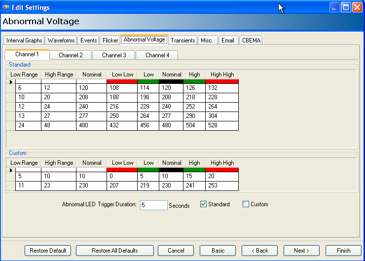
The Abnormal Voltage Report is used to determine whether the voltage drifted outside the thresholds during the recording session. Usually the Abnormal Voltage Report is used to get a quick read of whether there was any line voltage drift, if so, then other record types such as the Stripchart and Significant Change are used for more information. Use the timestamp to locate the events on the other reports and graphs.
The default threshold settings are at 5% and 10% of the nominal voltage (for example, 6 and 12 volts for the 120 volt nominal). The high threshold must be larger than the low threshold. The two custom nominals are preset at 106 and 230 volts, but should be changed if a different nominal is in use. The default trigger duration is five seconds, and can be set as small as one second, or as large as 255 seconds.
Older Model LED Behavior
Some older recorder models have LEDs on the front panel to indicate that there has been an abnormal voltage. If the low voltage threshold is exceeded, the green LED on the front panel is lit, likewise; if the high voltage threshold is exceeded, the red LED on the front panel is lit. There is a separate set of LEDs for each voltage channel.
Once an LED indicator is lit due to an Abnormal Voltage trigger, it stays on for the rest of the recording session, even if the voltage returns to the nominal. The LED indication of an Abnormal voltage trigger can be disabled through the software. The event is still recorded normally, but no LEDs are lit.
The LED indication of an Abnormal voltage trigger is changed in ProVision Settings Wizard on the Misc panel using the “LED Indicator” checkbox.
Conclusion
The Abnormal Voltage Report is used to determine whether the voltage drifted outside the thresholds during the recording session. Usually the Abnormal Voltage Report is used to get a quick read of whether there was any line voltage drift, if so, then other record types such as the Stripchart and Significant Change are used for more information.
There are five standard nominals (120, 208, 240, 277, and 480 volts), and two custom nominals. These are controlled using software settings. Several other reports use this nominal voltage for their triggering events.
Some older recorder models have LEDs on the front panel that indicated that there has been an abnormal voltage.
